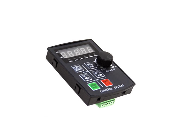
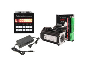
คำอธิบาย
ตัวควบคุมสเต็ปเปอร์มอเตอร์ ตัวควบคุมเซอร์โวมอเตอร์ การควบคุม Pulse การควบคุมความเร็ว การควบคุมการเคลื่อนที่แบบแกนเดียว ตั้งโปรแกรมได้ 1CH
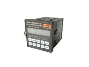
Stepper Motor Programmable Motion Control SH02 HF020 -RS485
- Voltage Input DC12-24V
- Dispaly 5 Digits
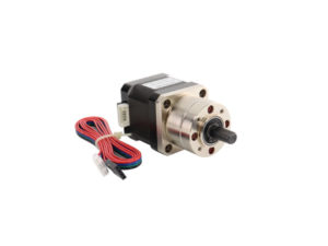
- ควบคุม Stepper Motor 1 ตัว
- ความถี่เอาต์พุตสูงสุด Maximum output frequency 85KHz
- ความละเอียดความถี่เอาต์พุต Output frequency resolution 1Hz
- Input 7 อินพุต สำหรับต่อสวิตช์ควบคุม (Opto-Isolation)
- Output 2 เอาต์พุต สำหรับต่อรีเลย์ข DC24V (Opto-Isolation)
- โปรแกรมสูงสุด 99 Step
- Communication RS485
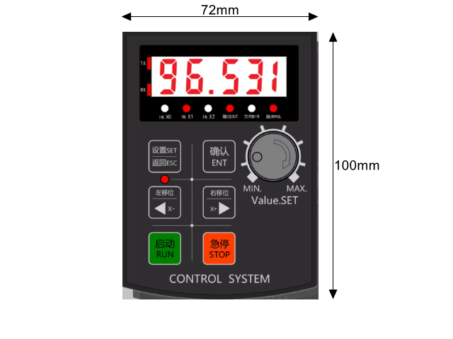
Dimension
การทำงาน
- การทำงานอัตโนมัติ, การดำเนินการด้วยตนเอง Manaul Jog, การแก้ไขโปรแกรม , การตั้งค่าพารามิเตอร์
การใช้งาน Function กล่องควบคุมสเต็ปเปอร์มอเตอร์ตั้งโปรแกรมได้ Programmable Motion Control SH02-1CH
- https://docs.google.com/spreadsheets/d/1T-JLL7g88L_UmB8IRcW0oErl1yGNPcYYyRX0RyNpZd8/edit?usp=sharing
1. เข้าใจระบบหน้าต่างการตั้งค่า ของกล่องควบคุม แบ่งหน้าต่างออกเป็น 3 ส่วนหลัก ได้แก่
- หน้าจอการทำงาน (Run interface)
- หน้าต่างตั้งค่าการทำงาน (ฟังก์ชันกลุ่ม P Function) สำหรับค่าที่ต้องปรับบ่อยๆ
- หน้าต่างตั้งค่าระบบ (ฟังก์ชันกลุ่ม F Function) สำหรับค่าระบบที่ไม่ต้องปรับบ่อย
2. P0 (Action mode)
เลือกลักษณะการทำงานที่ต้องการ (กำหนดค่า P0 ) นี่คือขั้นตอนแรกสุดที่ต้องเลือกว่า “อยากให้มอเตอร์ทำงานแบบไหน
- กดปุ่ม [ตั้งค่า/SET] เพื่อเข้าสู่เมนู หน้าจอจะแสดงผลที่พารามิเตอร์ P0 (Action mode)
- กดปุ่ม [ยืนยัน/ENT] เพื่อเข้าไปแก้ไขตัวเลขค่า P0
| P0 | NO. | Function | การทำงาน | Button |
| P0 | 1 | Motor working follows the knob direction | มอเตอร์ทำงานตามทิศทางของลูกบิด | |
| P0 | 2 | Keep rotating after pressing the RUN Button | หมุน หลังจากกดปุ่ม | RUN |
| P0 | 3 | Keep rotating after pressing the RUN Button, and stops when released | หมุน หลังจากกดปุ่ม และจะหยุดเมื่อปล่อยปุ่ม | RUN / STOP |
| P0 | 4 | Keep rotating after pressing the RUN Button, and stops when pressing RUN again | หมุนต่อไปหลังจากกดปุ่ม และหยุดเมื่อกดอีกครั้ง | RUN / STOP |
| P0 | 5 | After pressing the button, Motor forward rotate or reverse according to the set distance.(can set the cycle looping) |
หลังจากกดปุ่ม มอเตอร์หมุนเดินหน้าหรือถอยหลังตามระยะที่ตั้งไว้ (ตั้งรอบวนได้) |
RUN / STOP |
| P0 | 6 | After pressing the button, Motor forward rotate or return to zero according to the set distance. (Can be used for calibration) |
หลังจากกดปุ่ม มอเตอร์หมุนไปข้างหน้าหรือกลับเป็นศูนย์ตามระยะที่ตั้งไว้ (ใช้สำหรับการสอบเทียบ) |
|
| P0 | 7 | Always rotate forward or reverse, stop after hitting the limit switch wait for the next start |
หมุนไปข้างหน้าหรือย้อนกลับเสมอ หยุดหลังจากกดปุ่มลิมิตสวิตช์ รอการเริ่มต้นครั้งต่อไป |
|
| P0 | 8 | Forward and reverse according to the set distance (Cycle) | เดินหน้าถอยหลังตามระยะทาง และรอบ ที่ตั้งไว้ (Cycle) | |
| P0 | 9 | Forward and return to zero according to the set distance (Cycle) | เดินหน้าและกลับสู่ศูนย์ตามระยะทาง และรอบ ที่ตั้งไว้ (Cycle ) | |
| P0 | 10 | Forward and reverse between 2 limit switch (Cycle) | เดินหน้าและถอยหลังระหว่าง 2 ลิมิตสวิตช์ (Cycle) | |
| P0 | 11 | Press RUN button for first time motor forward, Press RUN button for second time, motor reverses | กดปุ่ม RUN ครั้งแรกให้มอเตอร์เดินหน้า กดปุ่ม RUN ครั้งที่สอง มอเตอร์ถอยหลัง | |
| P0 | 12 | Press RUN button for first time motor forward, Press RUN button for second time, motor reverses or returns to zero | กดปุ่ม RUN เพื่อเดินหน้ามอเตอร์ในครั้งแรก กดปุ่ม RUN เป็นครั้งที่สอง มอเตอร์จะถอยหลังหรือกลับสู่ศูนย์ | |
| P0 | 13 | Press RUN button first time, motor reverses and stops when it hits the limit switch. Press RUN button second time, motor forward and stops when it hits another limit switch |
กดปุ่ม RUN ครั้งแรก มอเตอร์จะถอยหลังและหยุดเมื่อถึงลิมิตสวิตช์ กดปุ่ม RUN ครั้งที่สอง มอเตอร์เดินหน้าและหยุดเมื่อถึงลิมิตสวิตช์อีกอัน |
|
| P0 | 14 | Press RUN button, motor forward, release RUN button, motor will immediately reverse or return to zero | กดปุ่ม RUN มอเตอร์ไปข้างหน้า ปล่อยปุ่ม RUN มอเตอร์จะถอยหลังหรือกลับสู่ศูนย์ทันที | |
| P0 | 15 | Press RUN button, motor keeps rotating forward, then delays, and keeps looping. Press RUN button again, motor returns to zero |
กดปุ่ม RUN มอเตอร์จะหมุนไปข้างหน้า จากนั้นหน่วง และวนซ้ำ กดปุ่ม RUN อีกครั้ง มอเตอร์จะกลับสู่ศูนย์ |
|
| P0 | 16 | Press RUN button, motor keeps rotating forward, then delays, and keeps looping. Press RUN button again, motor returns to zero |
กดปุ่ม RUN มอเตอร์จะหมุนไปข้างหน้า จากนั้นหน่วง และวนซ้ำ กดปุ่ม RUN อีกครั้ง มอเตอร์จะกลับสู่ศูนย์ |
|
| P0 | 17 | Press the RUN button, Press the set distance to rotate forward, release the RUN button, Motor immediately reverse or return to zero |
กดปุ่ม RUN กดระยะทางที่ตั้งไว้เพื่อหมุนไปข้างหน้า ปล่อยปุ่ม RUN มอเตอร์จะถอยหลังหรือกลับเป็นศูนย์ทันที |
|
| P0 | 18 | Press the RUN button Press the set time forward and reverse |
กดปุ่ม RUN กดตั้งเวลาเดินหน้าและถอยหลัง |
- P1: ตั้งค่าระยะทางเดินหน้า
- P2: ตั้งค่าความเร็วเดินหน้า
- P3: ตั้งค่าระยะทางถอยหลัง
- P4: ตั้งค่าความเร็วถอยหลัง หรือความเร็วตอนวิ่งกลับจุดศูนย์ (วิธีการตั้งค่าคือ เลื่อนไปที่ P1-P4 -> กด [ยืนยัน/ENT] -> เปลี่ยนตัวเลขระยะทางหรือความเร็ว -> กด [ยืนยัน/ENT] เพื่อบันทึกข้อมูล)
| P Function | No. | Function | Range | Default | |
| P | 0 | Action mode selection | การเลือกโหมดการทำงาน | 1-16 | 1 |
| P | 1 | < Forward distance (Depending on gear ratio) | < ระยะเดินหน้า (ขึ้นอยู่กับอัตราทดเกียร์) | 0.000~65535.999 | 10 |
| P | 2 | Forward speed | ความเร็วไปข้างหน้า | 0-65535 | 1500 |
| P | 3 | > Reverse distance (Depending on gear ratio) | > ระยะถอยหลัง (ขึ้นอยู่กับอัตราทดเกียร์) | 0.000~65535.999 | 10 |
| P | 4 | Reverse/Zero speed | ความเร็วถอยหลัง / ศูนย์ | 0-65535 | 1500 |
| P | 5 | Cycle work times (65535: countless times) | รอบการทำงาน | 0-65534 or countless times | 1 |
| P | 6 | Forward rotation delay | เวลา Delay ก่อน การหมุนไปข้างหน้า | 0.000~65535.999 | 0 |
| P | 7 | Reverse rotation delay | เวลา Delay ก่อน การหมุนย้อนกลับ | 0.000~65535.999 | 0 |
| P | 8 | Manual speed (X+ X-) | ตั้งค่าความเร็วแบบแมนนวล (X+ X-) | 0-65535 | 1000 |
4.ตั้งค่าระบบที่จำเป็น F Summary of functions: In actual work, the parameters (internal parameters of the system) that do not need to be modified frequently are all concentrated here.
- ไปที่ F1 และ F2 เพื่อตั้งค่าอัตราทดเกียร์อิเล็กทรอนิกส์ เพื่อให้ระยะที่มอเตอร์เลื่อนไปตรงกับตัวเลขบนหน้าจอ
- ไปที่ F20 ตั้งค่าเป็น 0 หรือ 1 เพื่อให้หน้าจอแสดงตำแหน่งระยะที่เลื่อนสะสมไว้โดยไม่ให้ค่าหายไป
| F Function | |||||
| F | No. | Function | Range | scope | |
| F | 1 | numerator (electronic gear ratio) The number of pulses equal to one revolution of the motor | 0-65535 | 160 | |
| F | 2 | Denominator (electronic gear ratio) How much um is equal to one revolution of the motor, 1mm = 1000um | 0-65535 | 100 | |
| F | 3 | Minimum speed (the minimum speed limit that the motor is allowed to run) Unit: class | 0-65535 | 0 | |
| F | 4 | Maximum speed (the maximum speed limit that the motor is allowed to run) Unit: level | 0-65535 | 65535 | |
| F | 5 | Homing position (useful only when mechanical zero point) Homing speed (useful only when mechanical zero point) | 0-65535 | 4 | |
| F | 6 | Homing speed (useful only when mechanical zero point) | 0-65535 | 150 | |
| F | 7 | Homing mode (0: software zero point 1-3: mechanical zero point, it is recommended to be 1. Do not use | 0-3 | 0 | |
| F | 8 | *Start point of zero point function (only useful for mechanical zero point) Unit: subject to gear ratio | 0-65535.999 | 65535 | |
| F | 9 | Acceleration (the acceleration level from the motor start to normal speed, the bigger the faster), the acceleration and deceleration values should be as consistent as | 0-65535 level | 2000 | |
| F | 10 | possible F10 *Deceleration (the deceleration level from the normal speed of the motor to the stop, the larger the faster) the addition and subtraction values should be as consistent as possible 0-65535 level | 0-255 | 2000 | |
| F | 11 | * System internal debugging parameters, do not set | 0-255 | 3 | |
| F | 12 | F12 * System internal debugging parameters, do not set | 0-65535 | 6400 | |
| F | 13 | *X0-X1-X2 input signal filter time When there is external interference, set it again, the larger the value, the slower the response | 0-65535 | 25 | |
| F | 14 | Amplitude of speed change during operation (change function can be turned off in F16) Unit: level | 0-255 | 3 | |
| F | 15 | Does it automatically return to zero when it is turned on? (0: not to return to zero when it is turned on 1: to return to zero automatically when it is turned on) | 0-1 | 0 | |
| F | 16 | *Special function setting this value must be converted to binary before it can be used If the value is 2, convert it to binary: 000000101 means open, 0 means close. All 0 – do not open any special functions normally (default value) 0-255 1st from the bottom – forcibly close the speed change function 1 – close the speed change 0 – open the speed change The second last digit-modify the motor rotation direction 1-change the direction 0- |
0-255 | 0 | |
| F | 17 | default direction F17 *Selective switch P interface or F interface 1-【P】【F】 2-on【P】off [F] 3-All off (Temporary open: Press the [Settings] key before turning on | 0-3 | 3 | |
| F | 18 | *Multiples of motor running speed, the larger the value of PSC, the slower the speed | 0-65535.999 | 3 | |
| F | 19 | *Multiple of acceleration and deceleration (for special cases, generally do not need to be set) The final acceleration and deceleration value = (F9: acceleration or F10: deceleration value) X (this value) |
1-255 | 1 | |
| F | 20 | Main interface display content 0-absolute position (positive and negative coordinates can be displayed) 1-absolute position (only positive coordinates can be displayed) 2- Relative position. That is to say, it will display the current state, and it will be cleared when the motor stops (positive and negative coordinates can be displayed) 3- Output pulse frequency (unit: KHZ) maximum error: ±1KHZ 0-6 4-Motor lap speed (unit: rev/min, maximum error ±90 rev/min. It needs to be filled in [F1] Real driver subdivision number, otherwise the display will be incorrect】》 5- Motor travel distance speed (unit: mm/s, the value of [F1] [F2] needs to be calculated in advance) |
0-6 | 0 | |
| F | 21 | Press the ESC (emergency stop) back button to execute. | 0-2 | 0 | |
| F | 22 | n/a | 24 | ||
| F | 23 | n/a | 0-65535 | ||
| F | 24 | Restore factory settings | 0-4 | 4 |
- กดปุ่มออกจากหน้าตั้งค่าเพื่อกลับมาที่ หน้าจอการทำงาน (Run interface)
- กดปุ่ม [เริ่ม/RUN] (ปุ่มสีเขียว) เพื่อสั่งให้มอเตอร์ทำงานตามโหมดที่ได้ตั้งโปรแกรมไว้
- ระหว่างที่มอเตอร์ทำงาน หากต้องการหยุดฉุกเฉินให้กดปุ่ม [หยุด/STOP] (ปุ่มสีแดง หรือ ESC)
- นอกจากการรันอัตโนมัติแล้ว ในหน้าจอปกติคุณยังสามารถกดปุ่ม [ซ้าย/X-] หรือ [ขวา/X+] ค้างไว้ เพื่อขยับมอเตอร์แบบแมนนวล (Manual) ด้วยตัวเองได้ โดยความเร็วแมนนวลนี้จะดึงมาจากค่าพารามิเตอร์ P8
Operation Mode

- P0→ 1 มอเตอร์ทำงานร่วมกับ Knob ปุ่มหมุนหน้ากล่อง
- P1 ปรับระยะทาง
- P2 ปรับความเร็ว
- P0→ 2 เมื่อกดปุ่ม X+ หรือ X- จะมีการเคลื่อนที่ไปเรื่อยๆจนกว่าจะกดปุ่ม Stop สีแดง
- P0→ 3 เมื่อกดปุ่ม X+ หรือ X- ค้างไว้จึงจะมีการเคลื่อนที่หากปล่อยปุ่มจึงจะหยุด
- P0→ 4 การควบคุมการเคลื่อนที่ ด้วยการกดปุ่ม X+ หรือ X- โดยมีลักษณะกดติดกดดับ
- P0→ 5 หลังจากกดปุ่ม X+ จะหมุนไปข้างหน้า หรือ กดปุ่ม X- จะหมุนไปข้างหลังตามระยะที่ตั้งไว้
- (X+ ปรับระยะทางได้ที่ P1 ปรับความเร็วได้ที่ P2)
- (X- ปรับระยะทางได้ที่ P3 ปรับความเร็วได้ที่ P4)
- P0→ 6 หลังจากกดปุ่ม X+ จะหมุนไปข้างหน้าตามระยะที่ตั้งไว้ และกดปุ่ม X- จะหมุนกลับมาที่ 0
- P1 ปรับระยะทาง
- P2 ปรับความเร็ว
- P0→7 หลังจากกดปุ่ม X+ หรือ X- จะหมุนไปข้างหน้าหรือข้างหลังตามความเร็วที่ตั้งไว้จนกว่าจะกดปุ่มหยุดสีแดงเหมาะสำหรับการทำ Speed Mode
- ปรับความเร็ว X+ ได้ที่ P2
- ปรับความเร็ว X- ได้ที่ P4
- P0→8 เมื่อกดปุ่ม Run สีเขียว การเคลื่อนที่วนไปข้างหน้าและถอยหลังตามระยะทางที่ตั้งไว้ การทำงาน LOOP
- เมื่อกดปุ่ม Run สีเขียว Output Y1 จะ ON
- เคลื่อนที่ไปข้างหน้าเป็นระยะทางเท่ากับ P1 ความเร็วเท่ากับ P2
- หลังจากนั้น Output Y1 OFF, Y0 ON
- หน่วงเวลาตามระยะเวลา P6
- Output Y1 ON, Y0 OFF
- หลังจากนั้นเคลื่อนที่กลับ เป็นระยะทางเท่ากับ P3 ความเร็วเท่ากับ P4
- หน่วงเวลาตามระยะเวลา P7
- หลังจากนั้น Output Y1 OFF
- LOOP ทั้งหมดจะวนจำนวนครั้งเท่ากับ P5
- P0→ 9 เมื่อกดปุ่ม Run สีเขียว การเคลื่อนที่วนไปข้างหน้าตามระยะทางที่ตั้งไว้ และถอยจะหมุนกลับมาที่ 0 การทำงาน LOOP
- เมื่อกดปุ่ม Run สีเขียว จะหมุนกลับมาที่ 0 (Home) ก่อนเริ่มเข้าสู่กระบวนการทำงาน
- หลังจากนั้น Output Y1 OFF
- การเคลื่อนที่ไปข้างหน้า ระยะทาง P1 ความเร็วเท่ากับ P2
- หลังจากนั้น Output Y1 ON, Y0 OFF
- หน่วงเวลาตามระยะเวลา P6
- Output Y1 ON, Y0 OFF
- หลังจากนั้นเคลื่อนที่กลับ มาที่ 0 ความเร็วเท่ากับ P4
- หลังจากนั้น Output Y1 OFF, Y0 ON
- หน่วงเวลาตามระยะเวลา P7
- หลังจากนั้น Output Y0 OFF
- LOOP ทั้งหมดจะวนจำนวนครั้งเท่ากับ P5
- P0→ 10 วนไปข้างหน้าและย้อนกลับระหว่างลิมิตสวิตช์สองตัว
- X0 คือ Home Limit Switch ด้านซ้าย
- X1 คือ Limit Switch ด้านขวา
- X2 ไม่ใช้
- P0→11 กดปุ่ม Run สีเขียว : จะหมุนไปข้างหน้าตามระยะที่ตั้งไว้ จากนั้น กดปุ่ม Run สีเขียว อีกครั้ง หมุนกลับตามระยะที่ตั้งไว้
- P0→12 กดปุ่ม Run สีเขียว : จะหมุนไปข้างหน้าตามระยะที่ตั้งไว้ จากนั้น กดปุ่ม Run สีเขียว อีกครั้ง ย้อนกลับกลับไปที่ศูนย์ (สามารถเปิดฟังก์ชันการสอบเทียบได้)
- P0→13 กดปุ่ม Run สีเขียว : จะหมุนย้อนกลับไปยัง Limit Switch เพื่อหยุด กดปุ่ม Run สีเขียว อีกครั้ง จะหมุนต่อไปยังลิมิตสวิตช์ตัวอื่นต่อไปเพื่อหยุด
- P0→14 กดปุ่ม Run สีเขียวค้างไว้ : จึงจะหมุนไปข้างหน้า – จนกว่าจะปล่อย จึงจะหมุนกลับมาที่ศูนย์
- P0→15 รอบการหมุนไปข้างหน้า N ครั้ง – จากนั้นย้อนกลับกลับไปที่ศูนย์
- P0→16 รอบการหมุนไปข้างหน้า N ครั้ง – จากนั้นย้อนกลับกลับไปที่ศูนย์
- P0→17 กดปุ่ม Run สีเขียวค้างไว้ : จึงจะหมุนไปข้างหน้าตามระยะที่ตั้งไว้ – จนกว่าจะปล่อย จึงจะหมุนกลับมาที่ศูนย์
- P0→18 เดินหน้าหรือถอยหลังตามเวลาที่ตั้งไว้
- P0→ 19 เดินหน้าหรือถอยหลังตามเวลาที่ตั้งไว้ Cycle
- Loop P5
- Time P6
- Delay P7
Terminal
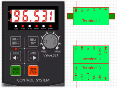
Terminal 1
- GND
- Input Switch X+
- Input Switch X-
- Output Y1
- RS485 A (Option*)
- RS485 B (Option*)
Terminal 2
- GND
- Input Switch X0
- Input Switch X1
- Input Switch X2
- Input Switch Start
- Input Switch Stop
Terminal 3
- V+ DC12-24V
- GND
- Vout (For Pule +, Dir +)
- Pule –
- Dir –
- Y0 Output
Wiring
Panel size 70x93mm
ในชุดประกอบด้วย
- กล่องควบคุมสเต็ปเปอร์มอเตอร์ Stepper Motor Programmable Motion Control

รีวิว
ยังไม่มีบทวิจารณ์