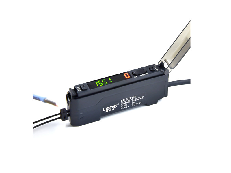
คำอธิบาย
ไฟเบอร์ออฟติกเซนเซอร์ LES-31P สามารถใช้ทดแทน FS-N18P, FS-N11P, FS-V11P Fiber Optic Sensor Amplifier ใช้สำหรับการตรวจจับวัตถุสี ตรวจสอบสีของผลิตภัณฑ์ในงานอุตสาหกรรม สามารถใช้กับบรรจุภัณฑ์ หลายประเภท เช่น ฟิล์มใส, ฟิล์มอลูมิเนียม, ถุงกระดาษ
ข้อมูลด้านเทคนิค
- Voltage Input DC12V-24V
- ประเภทเอาต์พุต Output PNP NO เมื่อตรวจจับวัตถุ เอาต์พุตเป็น Logic High
- Display 7-Segment
- Response time 50uS (HIGH SPEED) /250uS (Standard ) /500uS (Enhanced ) /1mS (Super)
- Multiple Expansion connections to 16units
- Optical sensor Light source Red, 4-Element LED
- Daylight 30,000 lux or less
- Mounted on DIN Rail
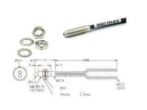
- Cable lenght 2M
ในชุดประกอบด้วย
- 1pcs x ไฟเบอร์ออฟติก เซนเซอร์ Fiber Optic Amplifier Sensor
- *ราคาไม่รวม สายโพรบ
Button function operation

Installation
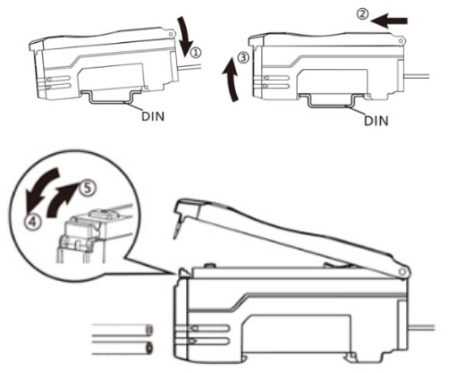
As shown in the figure below, snap the left side of the fiber optic sensor amplifier on the DIN rail and press the arrow (1) on the right side. Press hard in the direction of the head until you hear the locking sound.
DIN rail Disassemble
- As shown in the figure below, push the sensor unit in the direction of the arrow (2);
- Lift in the direction of the arrow (3) until you leave the guide rail.
Fiber optic connection
As shown in the figure below, open the protective cover and vibrate the locking lever down in the direction of the arrow (4) ; Insert the optical fiber into the corresponding position; Press the direction of the arrow (5) to move the locking lever upward to complete the connection. Send <, Receive >
Function setting
Restore factory
Press and hold the MODE and DOWN buttons at the same time and hold for 10 seconds or more to restore the factory settings
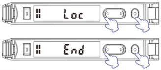
Lock-UnLock
Lock : Press and hold the MODE and UP buttons at the same time and hold for 3 seconds or more. When “Loc” is displayed, it is complete.
UnLock : Repeat the above operation again, and when “End” is displayed, the button lock is UnLock.
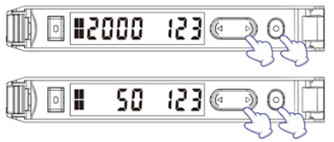
การตั้งค่าเกณฑ์ Threshold value setting
1. Manually set the Threshold value
- Need to be set when the optical fiber is fixed
- When no workpiece passes optical fiber, tap the SET button once
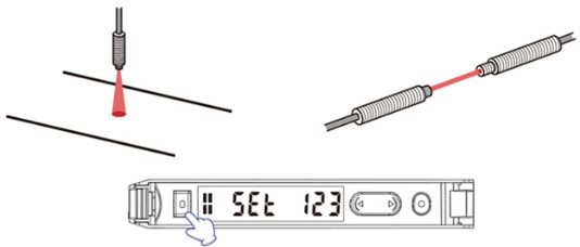
- When a workpiece passes optical fiber, tap the SET button again to complete the threshold setting.
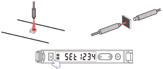
2. Automatically set the Threshold value
- It needs to be set if a workpiece passes through
- Press and hold the SET button until “SEt” starts to blink, and the value will be automatically taken, and the value will be taken for at least 3 seconds, the specific time depends on the speed at which the workpiece passes.

Function settings
- During the setting process, press and hold the MODE button on any interface for 3 seconds to return to the main interface.
- During the setting process, tap the MODE and UP combination buttons at the same time to return to the previous level.
- After selecting the delay mode, tap the SET button to enter the delay time setting.
การตั้งค่าอินเทอร์เฟซ Interface settings
Press and hold the O MODE button for 3 seconds to enter the settings interface.
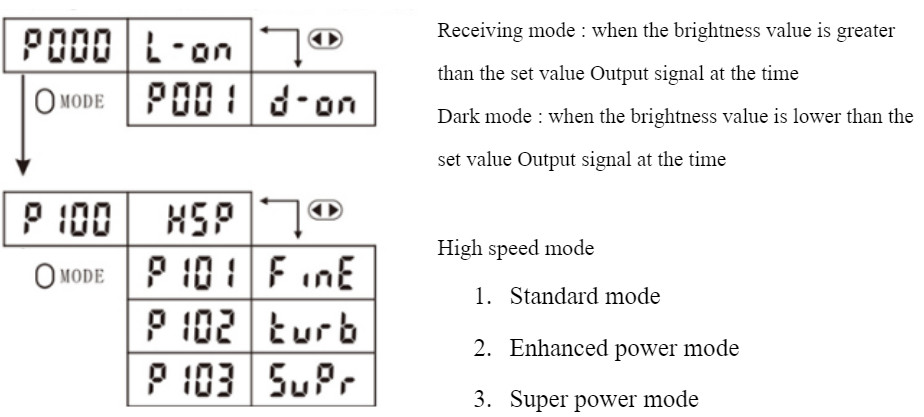
Light ON / Dark ON
- P000 = Light ON Mode
- P001 = Dark ON Mode
Response time
- P100 = Response time 50uS (High speed mode)
- P101 = Response time 250uS (Standard )
- P102 = Response time 500uS (Enhanced power mode)
- P103 = Response time 1mS (Super power mode)
P200 การส่องสว่างลำแสง 0 – 80
Anti-interference
- P300 Anti-interference off
- P301 Anti-interference
- P302 Submodule 1 (the host connection function takes effect)
- P303 Submodule 2 (the host connection function takes effect)
- P304 Submodule 3 (the host connection function takes effect)
P400 Delay Mode
| Display | Function introduction |
| P400 toFF | Disable the timer. (Default setting) |
| P401 1234 | Delay off-timer The output is turned off after 1234ms when the signal disappears. |
| P402 1234 | Delay on-timer The output is turned on 1234ms after the signal is detected. |
| P403 1234 | One-shot-timer The output is turned on when a signal is detected and turned off after 1234ms. |
P500 Low Power mode
- P501 Power Saving mode
- P502 Normal mode
Error message
| Display | Cause of error | Treatment method |
| Er: 00 | Load overcurrent | Cut off the power supply and check the load |
| Er: 01 | System damage | Replace the sensor |
การประยุกต์ใช้งาน
- ตรวจสอบสีในอุตสาหกรรมการผลิต
- ตรวจจับตำแหน่งมาร์คสี
- ตรวจสอบความเข้มสี
- ตรวจสอบความแตกต่างสี


รีวิว
ยังไม่มีบทวิจารณ์