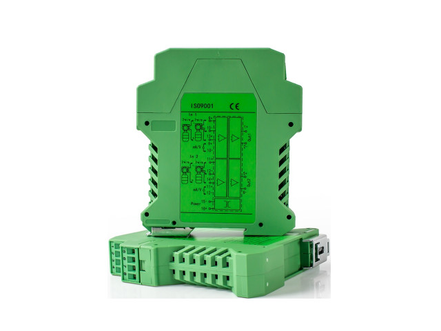
คำอธิบาย
4-20mA to RS485 Converter อุปกรณ์แปลงสัญญาณอะนาล็อก (Analog Signal Converter / Signal Isolator) ใช้สำหรับแปลงสัญญาณมาตรฐานอุตสาหกรรม เช่น 4–20mA, 0–10V, RS485 Modbus RTU ให้เข้ากันได้ระหว่างอุปกรณ์ควบคุมต่างๆ เช่น PLC, Controller, Sensor, และเครื่องบันทึกข้อมูล (Data Logger) โดยมีฟังก์ชันแยกกราวด์ (Isolation) เพื่อป้องกันสัญญาณรบกวนและแรงดันย้อนกลับ
Technical Specifications / ข้อมูลทางเทคนิค
- Input Signal 4-20 mA
- Output Signal RS-485
- Power Supply
- GLG DC 24 V
- Material ABS Engineering Plastic Enclosure Transformer: PCS core / TI USA core
- Output Impedance ≤ 50 Ω
- Load Resistance RL ≤ 500 Ω (output current), RL ≥ 1 kΩ (output voltage)
- Temperature Drift 0.005 % F.S / °C (−20 °C ~ 55 °C)
- Dielectric Strength 1500 V AC / 1 min (between input/output/power)
- Insulation Resistance ≥ 100 MΩ (between input/output/power)
- Accuracy 0.1 % F.S
- Response Time Millisecond level
คุณสมบัติเด่น
- ความแม่นยำสูง 0.1%
- ตอบสนองรวดเร็วระดับมิลลิวินาที
- แยกสัญญาณเต็ม 3 พอร์ต (Input / Output / Power)
- รองรับอินพุตแบบ 2-wire, 3-wire และ 4-wire
- Isolation สูง, อัตราแปลงเร็ว, ค่า drift ต่ำ
- มีให้เลือกหลายช่องสัญญาณ (1In 1Out, 1In 2Out, 2In 2Out, 2In 4Out)
ตัวแปลงสัญญาณ 4-20mA → RS485 คืออะไร อุปกรณ์ที่รับสัญญาณ 4-20mA Analog จากเซนเซอร์ เช่น
- Pressure Sensor
- Flow Sensor
- Temperature Sensor
- Level Sensor
- Sensor ฯลฯ
แล้วแปลงออกเป็น RS485 (Modbus RTU) เพื่อให้ PLC / SCADA / IoT Gateway อ่านค่าแบบดิจิทัลได้ เหมาะสำหรับระบบอัตโนมัติที่ต้องการความแม่นยำและส่งข้อมูลไกล
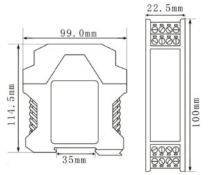
Dimension
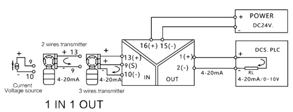
Wiring GLG
การใช้งานทั่วไป
- ระบบควบคุมอัตโนมัติ (Automation Control)
- การแปลงสัญญาณระหว่างอุปกรณ์วัดและ PLC / DCS
- การแยกสัญญาณกระแส 4–20 mA / แรงดัน 0–10 V เพื่อลดสัญญาณรบกวน
- งานในโรงงานอุตสาหกรรม / ระบบวัดค่ากระบวนการ (Process Monitoring)
การสื่อสาร RS-485 Modbus
1. พื้นฐานการสื่อสาร
- Interface: RS-485 (Half-duplex, Asynchronous)
- โหมด: 8 Data bits, 1 Start bit, 1 Stop bit, No parity
- ค่าเริ่มต้นจากโรงงาน:
- Address = 01H
- Baud rate = 9600 bps
-
Function Code ที่ใช้: 03 (Read Holding Register), 06 (Write Single Register)
2. รีจิสเตอร์หลัก
| Address | ชื่อ | R/W | คำอธิบาย |
|---|---|---|---|
| 0x000E | Process Value (PV) | Read | ค่ากระแส/แรงดันที่วัดได้ (-32767 ~ +32767)
|
| 0x0004 | Slave Address | Read/Write | 00 ~ FEH (255 Address)
|
| 0x0005 | Baud Rate Code | Read/Write | CH ~ 480H ตามตารางด้านล่าง |
3. Baud Rate Code Table
| Baud Rate (bps) | Code (Hex) |
|---|---|
| 1200 | 18H |
| 2400 | 30H |
| 4800 | 60H |
| 9600 | C0H |
| 19200 | 180H |
| 38400 | 240H |
| 57600 | 480H |
4. ตัวอย่างคำสั่งใช้งาน
อ่านค่าปัจจุบัน (PV) ที่ 0x000E → Function 03
เปลี่ยน Baud Rate → Function 06
เปลี่ยน 9600 → 4800 bps
5. ตัวอย่างสเกลค่ากระแส (0 ~ 20 A)
| Current Input (A) | Output (Hex) | Decimal | ค่าจริง (A) |
|---|---|---|---|
| 0 | 0000H | 0 | 0.00 |
| 4 | 018FH | 399 | 3.99 |
| 8 | 0320H | 800 | 8.00 |
| 12 | 04B1H | 1201 | 12.01 |
| 16 | 0642H | 1602 | 16.02 |
| 20 | 07D0H | 2000 | 20.00 |
6. การใช้งานจริง
- ตั้งค่า PLC/SCADA ให้ใช้พารามิเตอร์ 9600 bps, 8N1 (Default)
- Poll register 0x000E (1 reg, FC03) ทุก 200–500 ms
- แปลงค่าที่อ่านได้เป็น Unsigned 16-bit → คูณ 1/100 เพื่อได้หน่วยจริง (A หรือ V)
- เขียนค่า Address/Baud ด้วย FC06 (0x0004/0x0005) → รีสตาร์ทไฟ
คำแนะนำการนำไปใช้ (PLC / SCADA / Node-RED)
- Serial Setting: 9600 bps / 8 N 1 (Half-duplex RS-485)
- Poll Interval: 200 – 500 ms
- Read Command: FC 03 → Reg 0x000E (1 reg)
- Scale Value: ค่าที่อ่านได้ ÷ 100 → หน่วยจริง (A หรือ V)
- Write Config: ใช้ FC 06 → 0x0004 / 0x0005 → Restart Power หลังเขียน


รีวิว
ยังไม่มีบทวิจารณ์