Posted on

ความรู้เบื้องต้นเกี่ยวกับ proximity sensor switches

ความรู้เบื้องต้นเกี่ยวกับ proximity sensor switches

  • Inductive proximity sensor switch ตรวจจับวัตถุโลหะ (เช่น เหล็ก เหล็กกล้า ทองแดง ฯลฯ)
  • Capacitive proximity sensor switch ตรวจจับวัตถุวัตถุ (เช่น แก้ว โลหะ พลาสติก น้ำ น้ำมัน กระดาษ ฯลฯ)
  • พร็อกซิมิตี้สวิตช์แบบฮอลล์ วัตถุตรวจจับเป็นโลหะแม่เหล็ก (เช่น แม่เหล็กถาวร)
  • Diffuse reflection photoelectric sensor switch ตรวจจับวัตถุวัตถุ (วัตถุโปร่งใสและทึบแสง) เช่น: โต๊ะ ผนัง กระจกใส แผ่นโลหะ ฯลฯ

ประเภท NPN คืออะไร และประเภท PNP คืออะไร

ประเภท NPN

  • การเชื่อมต่อโหลด เชื่อมต่อโหลดระหว่างขั้วเอาท์พุท Sensor และขั้วลบ – ของแหล่งจ่ายไฟ (Vcc)
  • ระดับเอาต์พุต เมื่อไม่มีการตรวจจับ เอาต์พุตจะอยู่ในระดับสูง Hi (Vcc) และเมื่อมีการตรวจจับ เอาต์พุตจะอยู่ในระดับต่ำ Lo (0V)
  • ทิศทางกระแส กระแสโหลดไหลเข้า Sensor (Sinking current)

ประเภท PNP

  • การเชื่อมต่อโหลด เชื่อมต่อโหลดระหว่างขั้วบวก + ของแหล่งจ่ายไฟ (Vcc) และเอาต์พุต Sensor
  • ระดับเอาต์พุต เมื่อไม่มีการตรวจจับ เอาต์พุตจะอยู่ในระดับต่ำ Lo (0V) และเมื่อมีการตรวจจับ เอาต์พุตจะอยู่ในระดับสูง Hi (Vcc)
  • ทิศทางกระแส กระแสโหลดไหลออกจาก Sensor (Source current)

ความแตกต่างระหว่างปกติ เปิด (NO) และปกติ ปิด (NC)

  • 1. ปกติเปิด (NO) หมายความว่า สัญญาณเอาต์พุต ถูกเปิดวงจรในสถานะปกติ ไม่มีการส่งสัญญาณเอาต์พุต และจะปิดวงจรเมื่อตรวจพบวัตถุ และสัญญาณเอาต์พุตจะถูกส่งออก
  • 2. ปกติปิด (NC) หมายความว่า สัญญาณเอาต์พุต อยู่ในสถานะปิดวงจรภายใต้สภาวะปกติ และมีการส่งสัญญาณเอาต์พุต เมื่อตรวจพบวัตถุ จะเปิดวงจร และสัญญาณเอาต์พุตจะไม่ถูกส่งออก

วิธีการเดินสายไฟแบบ 3 สาย

  1. สีน้ำตาลเชื่อมต่อกับขั้วบวกของแหล่งจ่ายไฟ
  2. สีน้ำเงินเชื่อมต่อกับขั้วลบของแหล่งจ่ายไฟ
  3. สีดำเชื่อมต่อกับโหลด (เอาต์พุตสัญญาณ)

วิธีการเดินสายไฟสองสาย (DC หรือ AC)

  1. สายสีน้ำตาลเชื่อมต่อกับขั้วลบของโหลด บวกของโหลดเชื่อมต่อกับขั้วบวกของแหล่งจ่ายไฟ
  2. สายสีน้ำเงินเชื่อมต่อโดยตรงกับขั้วลบของแหล่งจ่ายไฟ
Posted on

ควบคุมสเต็ปปิ้งมอเตอร์โดยใช้บอร์ดอาดูโน่และลิมิตสวิทช์

ควบคุมสเต็ปปิ้งมอเตอร์โดยใช้บอร์ดอาดูโน่

#define Go_L 8 // กำหนดขาที่ต่อกับสวิตช์โยก
#define Go_R 9 // กำหนดขาที่ต่อกับสวิตช์โยก
#define Limit_R 11 //กำหนดขาที่ต่อกับลิมิตสวิทช์
#define Limit_L 12 //กำหนดขาที่ต่อกับลิมิตสวิทช์
int speed1 = 900; //กำหนดความเร็ว ค่าน้อย มอเตอร์หมุนเร็ว ค่ามาก มอเตอร์หมุนช้า
void setup(){  
  pinMode(5, OUTPUT);
  pinMode(2, OUTPUT);
  pinMode(Go_L, INPUT_PULLUP);
  pinMode(Go_R, INPUT_PULLUP);
  pinMode(Limit_R, INPUT_PULLUP);
  pinMode(Limit_L, INPUT_PULLUP);     
}
void loop() {
if(digitalRead(Go_R)==0)  //โยกไปขวา
      {
            if (digitalRead(Limit_R))//ตราบเท่าที่ยังไม่ชนลิมิตสวิตช์ สั่งให้มอเตอร์หมุนต่อไป
            {
                digitalWrite(2, LOW);
                digitalWrite(5, HIGH);
                delayMicroseconds(speed1);
                digitalWrite(5, LOW);
                delayMicroseconds(speed1);  
            }  
            else
            {
              // ชนลิมิตสวิตช์แล้ว มอเตอร์หยุด
            }
      }
  if(digitalRead(Go_L)==0) //โยกไปซ้าย
      {          
            if (digitalRead(Limit_L))//ตราบเท่าที่ยังไม่ชนลิมิตสวิตช์ สั่งให้มอเตอร์หมุนต่อไป
            {
                 digitalWrite(2, HIGH);
                digitalWrite(5, HIGH);
                delayMicroseconds(speed1);
                digitalWrite(5, LOW);
                delayMicroseconds(speed1); 
            }  
            else
            {
              // ชนลิมิตสวิตช์แล้ว มอเตอร์หยุด
            }
      }
}


Posted on

บันทึกข้อมูล CoolTerm Arduino Serial Motitor Data ในไฟล์ TXT, CSV และ Excel

ใช้ CoolTerm เพื่อรับข้อมูลซีเรียลเป็นไฟล์ที่บันทึกได้

CoolTerm 2.0 freeware Download

https://coolterm.en.lo4d.com/windows

CoolTerm สามารถบันทึกข้อมูลขาเข้าลงในไฟล์ข้อความ ในส่วนวิธีใช้ คุณสามารถอ่านเกี่ยวกับ “ข้อมูลที่ได้รับสามารถบันทึกลงใน Textfile โดยใช้การ Connection/Capture to Textfile.”, “Capture Text Options”, “Leave File open while capturing” and “Add timestamps to received data”.

Posted on

Virtual Serial COM Port

Virtual COM port (หรือ Virtual Serial Port) คือ การจำลองพอร์ต COM ของคอมพิวเตอร์เพื่อให้สามารถเชื่อมต่อกับอุปกรณ์ภายนอกที่ใช้สื่อสารแบบซีเรียลได้ โดยใช้ซอฟต์แวร์ที่ช่วยทำหน้าที่จำลองพอร์ต COM ขึ้นมา เพื่อสร้างสายสัญญาณควบคุมการสื่อสารระหว่างคอมพิวเตอร์กับอุปกรณ์ภายนอก

ตัวอย่างของซอฟต์แวร์ที่ใช้ Virtual COM port เช่น Serial-to-Ethernet Converter ซึ่งเป็นเครื่องมือที่ช่วยแปลงสัญญาณซีเรียลเป็นสัญญาณเครือข่ายแบบ Ethernet ซึ่งสามารถเชื่อมต่อกับคอมพิวเตอร์ผ่านทาง Virtual COM port ได้

Virtual Serial Port Emulators

HW VSP3 – Virtual Serial Port

HW VSP is a software driver that adds a virtual serial port (e.g. COM5) to the operating system and redirects the data from this port via a TCP/IP network to another hardware interface, which is specified by its IP address and port number.

Licence type: Freeware

pass : admin

Serial Test reslut Method 1 Arduino

Serial Test reslut Method 2 Hercules


Virtual COM Port Driver software (https://www.netburner.com/)

https://www.netburner.com/learn/how-to-create-a-virtual-serial-port/


Posted on

เครื่องมือสำหรับนักพัฒนาดีบักเกอร์ TCP Debugger Developer tools

เครื่องมือดีบัก tcp ที่สามารถใช้เป็นไคลเอนต์ tcp หรือเซิร์ฟเวอร์ tcp
ข้อจำกัดการใช้งานสำหรับผู้ใช้ฟรี: จะมีการสนทนารอ 10 วินาทีก่อนที่จะส่งข้อมูล

–  สามารถส่ง content ข้อความที่ระบุ สตริงเลขฐานสิบหก เทมเพลตข้อมูล หรือแม้แต่เนื้อหาไฟล์ไปยังอุปกรณ์ระยะไกล

– ดู content ไบต์ในรูปแบบเลขฐานสิบหกเพื่อตรวจสอบว่าเนื้อหาถูกต้องหรือไม่


TCP Debugger

Wuhan Bami Technology Co., Ltd.

https://apps.microsoft.com/store/detail/tcp-debugger/9NWV1TCX232T?hl=en-us&gl=us


Posted on

การหาความยาวรอบวงสายพานไทม์มิ่ง XL หน่วยเป็น mm.

สายพานไทมิ่ง (Timing Belt) เป็นสายพานที่ใช้งานในระบบเครื่องยนต์ สายพานไทมิ่งเบอร์ XL มีขนาดระยะพิทช์ (pitch) เท่ากับ 5.08mm.

การแปลงสายพานไทม์มิ่งเบอร์ XL เป็นความยาวรอบวงของสายพาน

L = (XL/2)xP

โดยที่

  • L = ความยาวรอบวง หน่วย mm.
  • XL = เบอร์ สายพานไทม์มิ่ง
  • T = จำนวนฟันของสายพาน = (เบอร์ สายพานไทม์มิ่ง) / 2 = XL/2
  • P = ระยะพิทช์ (pitch) เท่ากับ 5.08mm.

ตัวอย่างเช่น หากต้องการแปลงสายพานไทม์มิ่งเบอร์  100XL หรือ XL100 เป็นความยาวรอบวง หน่วย mm.

L = (100/2)x5.08

ความยาวรอบวงพานไทม์มิ่งเบอร์ 100XL หรือ XL100 = 254 mm.

Posted on

Wlkata Firmware Upgrade

Mirobot robotic arm firmware upgrade :

Method 1

1. Turn on the robot arm and plug the USB cable into the robot arm.

2. Open WLKATA Studio, enter Settings , select Mirobot and click Update Firmware .

Mirobot robotic arm firmware upgrade :

Method 2

1. Turn on the robot arm and plug the USB cable into the robot arm.

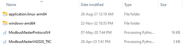
2. Find the “updatehex” folder in the root directory of “WlkataStudio”. As shown in Figure 17-5.

3. After opening “updatehex”, find “XLoader” and open it. As shown in Figure 17-6.

4. Open ” XLoader ” and select the latest robot arm firmware downloaded . As shown in Figure 17-7.

5. After selecting the arm firmware , click the ” Upload ” option. As shown in Figure 17-8.

Multifunction controller firmware upgrade :

Method 1

1. Turn on the robotic arm and plug the USB cable into the multi-function controller .

2. Find the “controlbox” folder in the root directory of “WlkataStudio”. As shown in Figure 17-10.

3. Open the folder “controlbox”, find and open the folder “bin file”. As shown in Figure 17-11

4. Double-click to open the folder “binfile”, as shown in Figure 17-12(1). Then put the firmware you just downloaded into it, delete the old version of the firmware, and only keep the latest firmware. As shown in Figure 17-12(2).

5. Open WLKATA Studio, enter the settings , click update firmware behind the multi-function controller firmware .

Method 2

1.. Turn on the robotic arm and plug the USB cable into the multi-function controller .

2. Install “flash_download_tool_3.8.8” and open the software.

3. After opening the software, a window will pop up, as shown in Figure 17-15.

Select ” ESP32 ” in the “Chip Type” column , as shown in Figure 17-16(1)

Select ” factory ” in the “Work Mode” column , as shown in Figure 17-16(2).

Click ” ok ” to go to the next step

4. The page is now locked and needs to be manually unlocked. Uncheck ” LOCK SETTINGS “. As shown in Figure 17-17.

The red box is the multi-function controller firmware (c-), and the blue box is the Bluetooth teach pendant firmware (t-). Here we don’t consider the teach pendant, only choose the controller. The address below is 0x00 by default .

Select the downloaded latest multi-function controller firmware to load

Select the robot port , and select 921600 as the baud rate . Figure 17-19

Then click the ” Start ” button. Figure 17-20

Posted on

ตัวอย่างโปรแกรม แสดงผล Counter บนคอมพิวเตอร์ Modbus RTU RS485 ด้วย Software Processing 

โปรโตคอล Modbus เป็นวิธีการมาตรฐานในอุตสาหกรรมสำหรับการถ่ายโอนข้อมูล ใช้กับระบบอัตโนมัติและระบบควบคุมในงานอุตสาหกรรม

  • Step 3 : เชื่อมต่อสายสื่อสารข้อมูล RS485-USB เข้ากับคอมพิวเตอร์
  • Step 4 : เปิด Source Code เปลี่ยน Comport ให้ตรง (ทำได้โดยแก้ไขบรรทัดที่  3 เดิมเป็น COM11 เปลี่ยน commPort เป็น COMXX ให้ตรงกับ Comport ในคอมพิวเตอร์ของเรา *ดูใน Device Manager )
import processing.serial.*;
Serial myPort; // create a Serial port instance
String commPort = "COM11";
int baud = 9600;
char parity = 'N';
int dataBits = 8;
float stopBits = 1.0;

ModbusPort port_one; // create a Modbus port instance
int timeout = 500;
int polling = 100;
int no_of_retries = 10;
int total_no_of_packets = 2;

Packet[] packets = new Packet[total_no_of_packets]; // create an array of packets to transmit
int[] readRegs1  = new int[2]; // to store the requested data
int[] readRegs2  = new int[2]; // to store the requested data
//int[] readRegs3  = new int[2]; // to store the requested data

int previousMillis = 0;
int count = 0;
void setup(){
  size(1024, 768);

  myPort = new Serial(this, commPort, baud, parity, dataBits, stopBits);   // initialize the Serial port instance
  port_one = new ModbusPort(myPort, timeout, polling, no_of_retries, packets, total_no_of_packets);   // initialize a port for modbus communications

  // The packet format for function 1, 2, 3, 4, 15 & 16 is:
  // Packet(id, function, address, data, data array)

  packets[0] = new Packet(1, 03, 01, 1, readRegs1);  //(ID, FNC READ_HOLDING_REGISTERS = 3, ADD (00=Target) (36=Count), data, data array)
  packets[1] = new Packet(1, 03, 15, 1, readRegs2);  //(ID, FNC READ_HOLDING_REGISTERS = 3, ADD (00=Target) (36=Count), data, data array)
  //packets[2] = new Packet(1, 03, 31, 1, readRegs3);  //(ID, FNC READ_HOLDING_REGISTERS = 3, ADD (00=Target) (36=Count), data, data array)

}

void draw(){  
  background(200);
  port_one.update();
  // Display the registers received using function 3
  
  fill(255, 0, 0); // RGB Color
  textSize(50); 
  text("Counter Machine S2-Innovation", 40, 50);
  
  fill(0, 255, 0); // RGB Color
  textSize(200); 
  text("TARGET : "+readRegs1[0], 50, 300);
  
  fill(0, 0, 255); // RGB Color  
  textSize(200);
  text("ACTUAL : "+readRegs2[0], 50, 600);

  //text("OUT    :" +readRegs3[0], 10, 1200);
    
}

Step 5 : กดปุ่มรัน (Run) โปรแกรมจะแสดงผลค่า Target และค่าที่นับได้ (Actual)

Posted on

การแปลงนิวตัน-เมตร (N-m) เป็นกิโลกรัม-เซนติเมตร (kg-cm)

ในการแปลงนิวตัน-เมตร (N-m) เป็นกิโลกรัม-เซนติเมตร (กก.-ซม.)  สามารถใช้ การแปลงต่อไปนี้:

1 N-m = 100 kg-cm

ดังนั้น หากต้องการแปลงค่าจาก N-m เป็น kg-cm ให้คูณค่าด้วย 100

ตัวอย่างเช่น ถ้ามีค่าแรงบิด 20 N-m เราสามารถแปลงเป็น kg-cm ได้ดังนี้:

20 N-m * 100 kg-cm/N-m = 2000 kg-cm

ดังนั้น 20 N-m เท่ากับ 2,000 kg-cm

Posted on

Learning Steps and Time elephantrobotics myCobot 280 M5 Robot Arm

Learning Steps and Time elephantrobotics myCobot 280 M5 Robot Arm

No. Target knowledge points Theory Practice Estimated hours of learning
1 Quick unpacking 1 Drag teaching 1. The accessories for myCobot
2. drive the robot to perform drag teaching
1 hour
2 Background knowledge learning 1. Use background of industrial robots;
2. coordinate and space learning, and Cartesian 3D coordinate and rotation, xyz;
3. joint and coordinate control of industrial robots
1. Joint control and recurrence of robot joints
2. speed control of robots
3. control and cycle of robot coordinate points
5 hours
3 Hardware learning 1. Principles and operations of embedded electronics
2. the principle and knowledge of servo and motor
3. actuator learning
1. Basic/atom control and driving
2. driving and motion of servo
3. robot accessory learning
5 hours
4 Software and firmware and their updating 1. Identify different software platforms and their use
2. firmware loading and adaptation principle
1. Select the developing platform suitable for you
2. load and update the corresponding firmware.
2 hours
5 Building of software development environment 1. Build Arduino platform
2. load and update of Arduino library file
3. understand serial communication
1. Familiar with Arduino platform
2. load a library
3. operate and run the first line of codes
2 hours
6 Learning and development of robot library 1. Basic communication and operation types of robots
2. common operating methods of robots
3. control of direction and coordinate modes
1. Communicate with the robot
2. control the robot to move
3. operate the IO interface, gripper, etc. of the robot;
5 hours
7 myBlockly operation robot arm 1. Understand the basic architecture and relation of graphical programing language interfaces: sensor, actuator and procedure
2. variable, cycle and judgment
3. control method of robot arm
1. Display different fonts in the basic
2. make the robot arm move to different positions using three buttons of the basic
3. control the robot arm to make it move to several positions circularly
10 hours
8 The use of roboFlow 1. Learn the industrial operating systems commonly used for robots
2. learn the common modules for roboFlow: point, quick movement, IO control and output
3. learn the advanced modules of roboFlow: cycle, judgment, and pallet program
1. Control the movement of the robot arm
2. basic control of IO input and output
3. cycle control and judgmen
5 hours
9 Algorithms related to image recognition 1. Common color recognition methods and strategies
2. common shape recognition methods and strategies
3. common area recognition methods and strategies
1. Building of a ROS environment
2. reading of different colors
3. recognition of different shapes
20 hours
10 Vision and the joint debugging of the robot 1. Connect the world with a camera coordinate system
2. QR code image calibration
3. movement and correction
1. Operate the robot arm to the camera coordinate system
2. the robot arm moves in the camera coordinate system
3. recalibrate and set
10 hours
11 Artificial intelligence (AI) package 1. Flow chart learning and making
2. electrical connection diagram learning and making
3. operation strategies such as image recognition and classification, etc
1. Sensor connection
2. gripper actuator connection and driving
3. robot arm driving and visual joint debugging
20 hours


Docs

  • https://docs.elephantrobotics.com/docs/gitbook-en/3-RobotKnowledge/3.1-series_robot.html