วิธีการใช้งาน Arduino Opta PLC อย่างง่าย
- พูดถึง Ardunio เป็นแพลตฟอร์มยอดนิยมของคนที่สนใจการเขียนโปรแกรมเพื่อควบคุมฮาร์แวร์ทั้งในแบบเป็นงานอดิเรก หรือแม้กระทั้งนำไปใช้ในระดับมืออาชีพ แต่สำหรับ Arduino Opta PLC ตัวนี้ เพิ่งเปิดตัวมาได้ไม่นาน มันเกิดจากความร่วมมือกันระหว่าง Arduino และผู้ผลิตPLC ที่มีชื่อดังยี่ห้อ Finder ต่อไปเราจะเรียก PLC ตัวนี้ สั้นๆ ว่า Opta อ่านว่า ออปต้า
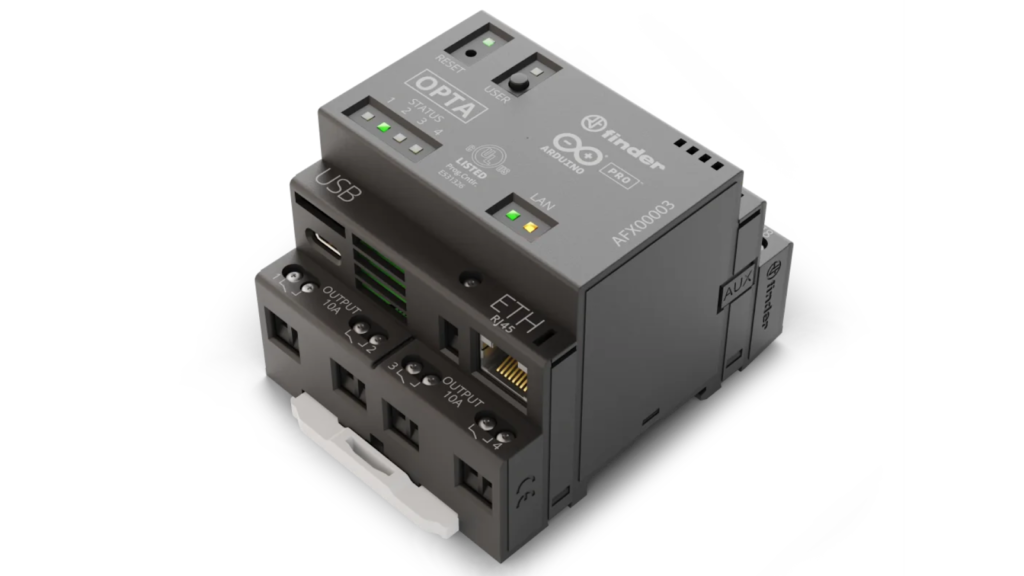
รูปที่1
- ในปัจจุบัน Opta มีทั้งหมดสามรุ่นได้แก่ Opta Lite, Opta RS485, และ Opta WiFi ในบทความนี้จะได้ทดลองใช้ Opta RS485 หมายถึง ในรุ่นนี้จะมีช่องทางการสื่อสาร RS485 ให้ด้วยที่จะมีประโยชน์มาก ซึ่งจะกล่าวเพิ่มเติมในภายหลัง
- แพลตฟอร์ม Arduino ที่ได้รับการจดจำมากที่สุดตลอดกาลตอนนี้ก็คือ Arduino Uno มันสามารถทำให้ผู้ที่ยังไม่เคยใช้งานการเขียนโปรแกรมมาก่อนสามารถเริ่มต้นได้อย่างรวดเร็ว รวมถึงการมีไลเบอรีจำนวนมากให้สามารถนำมาต่อยอดใช้งานได้ทันที ที่สำคัญคือฮาร์ดแวร์ที่เป็นมาตรฐานลดระยะเวลาที่ต้องออกแบบ PCB ใหม่ ทั้งหมดทำให้ผู้ใช้สามารถใช้งานได้ง่ายและนำไปต่อยอดได้อย่างรวดเร็ว
- จากที่กล่าวมาทั้งหมดนี้ ผู้ผลิตสัญญาณว่า จะนำแนวคิดที่กล่าวมาข้างต้นนี้ มาใช้กับArduino Opta เช่นเดียวกัน โดยสามารถรองรับการเขียนโปรแกรมบน Arduino IDE และได้เพิ่ม PLC IDE ที่สามารถรองรับภาษา PLC ตามมาตรฐาน IEC 61131-3 ซึ่งเป็นภาษาที่ใช้ในการเขียนโปรแกรม PLC ที่ช่างเทคนิค วิศวกร ต่างๆ คุ้นเคยกันอยู่แล้ว ผมคิดว่า ทาง Arduino พยายามที่นำ แพลตฟอร์ม Arduino เข้าสู่โลกของอุตสาหกรรม ที่ต้องการความน่าเชื่อถือ ความเข้ากันได้ของอินพุตและเอาต์พุต ร่วมถึงภาษาที่ใช้ในการพัฒนาซึ่งบุคคลากรในอุตสาหกรรมคุ้นเคยกันอยู่แล้ว
ผมสามารถสรุปข้อดีของ Arduino Opta ได้ดังนี้
- สามารถเขียนโปรแกรมแบบคลาสสิค ด้วยภาษาซี บน Arduino IDE หรือจะใช้ PLC IDE ซึ่งเขียนด้วยภาษา PLC ตามมาตรฐาน IEC 61131-3 ก็ได้ แล้วแต่ความถนัดของผู้ใช้งาน
- รองรับโปรโตคอลการสื่อสาร Fieldbus และ Modbus
- รองรับ WiFi (เฉพาะรุ่นที่มี)
- รองรับ Arduino Cloud
- มีการออกแบบที่ทนทาน พร้อมตัวยึดรางแบบ Dinrail
คุณลักษณะของ Arduino Opta
ในส่วนนี้ เราจะมีสำรวจสเปคของ Arduino Opta กัน ซึ่งสามารถทำตารางสรุปได้ดังนี้

รูปที่2
โดยทุกรุ่นมีสเปคคร่าวๆ ดังนี้
- แรงดันไฟเลี้ยง สามารถใช้ได้ตั้งแต่ 12 ถึง 24 โวลต์
- อินพุต 8 ช่อง สามารถกำหนดเป็น ดิจิตอล อินพุต หรือ เป็นอนาลอกอินพุต ก็ได้
- เอาต์พุตเป็น รีเลย์ 4 ช่อง หน้าสัมผัสทดกระแสได้ 10 แอมป์
- ตัวประมวลผล เป็นแบบแกนคู่ จาก ST เบอร์ STM32H747XI
- หน่วยความจำแรม 1 เมกะไบต์
- หน่วยความจำแฟลต 2 เมกะไบต์
อินพุตของ Arduino Opta
- ตามเอกสารจากดาต้าชีส ตัว Opta สามารถกำหนดอินพุตให้สามารถรับได้ทั้งอนาลอกและดิจิตอล โดยเมื่อกำหนดให้อินพุตเป็นแบบดิจิตอล สามารถรองรับสัญญาณ LOW หรือ HIGH ได้ แต่เมื่อกำหนดเป็นอินพุตอนาลอก สามารถรองรับแรงดัน 0 ถึง 10 โวลต์ดีซี
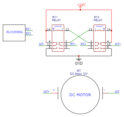
เอาต์พุตของ Arduino Opta
- เอาต์พุตของ Opta เป็นหน้าสัมผัสรีเลย์แบบ ปกติเปิด (normally open NO) โดยรีเลย์แต่ละตัวจะมีหน้าสัมผัสทนกระแสได้ 10A 250VAC
ทดลองเขียนโปรแกรมภาษาซี บนArduino IDE
- เราสามารถเขียนโปรแกรมภาษาซีบน Arduino IDE แล้วโปรแกรมเข้าไปยังตัว Opta ได้แบบเดียวกับบอร์ด Arduino ทั่วไป ในบทความนี้ได้ทดสอบบน Arduino IDE 2.0.4
- เมื่อเปิด Arduino IDE ขึ้นมา ให้ไปที่ Tools à Board à Board Manager
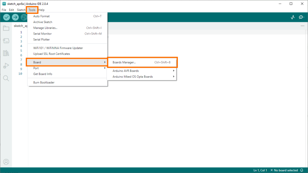
รูปที่ 3
ในช่องค้นหา ใส่คำว่า opta มองหา Arduino Mbed OS Opta Boards by Arduino จากนั้นคลิ๊กติดตั้งให้เรียบร้อย
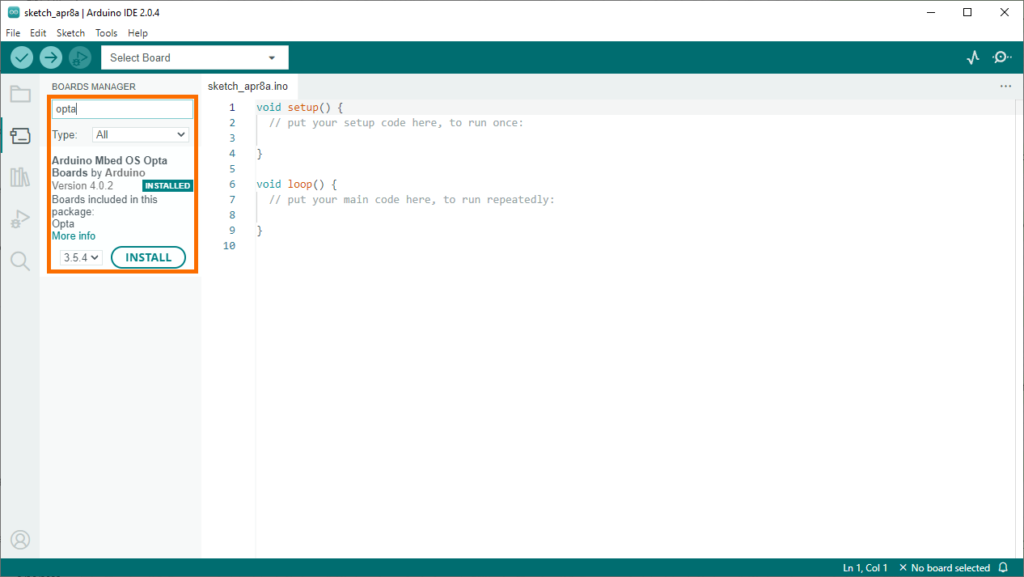
รูปที่ 4
- ขั้นต่อไป กลับมาที่ ตัว Opta ให้ต่อสายไฟเลี้ยงเข้า สามารถใช้ได้ตั้งแต่ 12 ถึง 24 โวลต์ ให้สังเกตดีๆ เพราะมีช่องบวก สองช่อง ช่องลบ สองช่อง
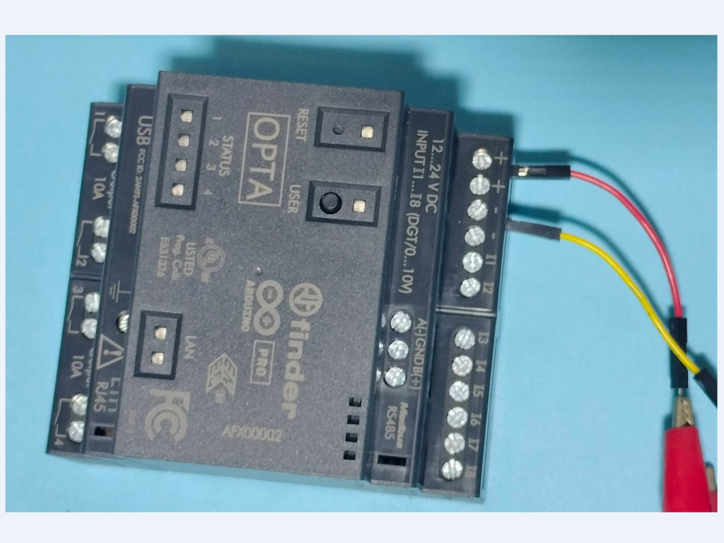


รูปที่ 5
- สุดท้ายเป็นการต่อสาย USB type C เข้ากับตัว Opta สายนี้ใช้เพื่อโหลดโค้ดและมอนิเตอร์ค่าระหว่างการทำงานได้
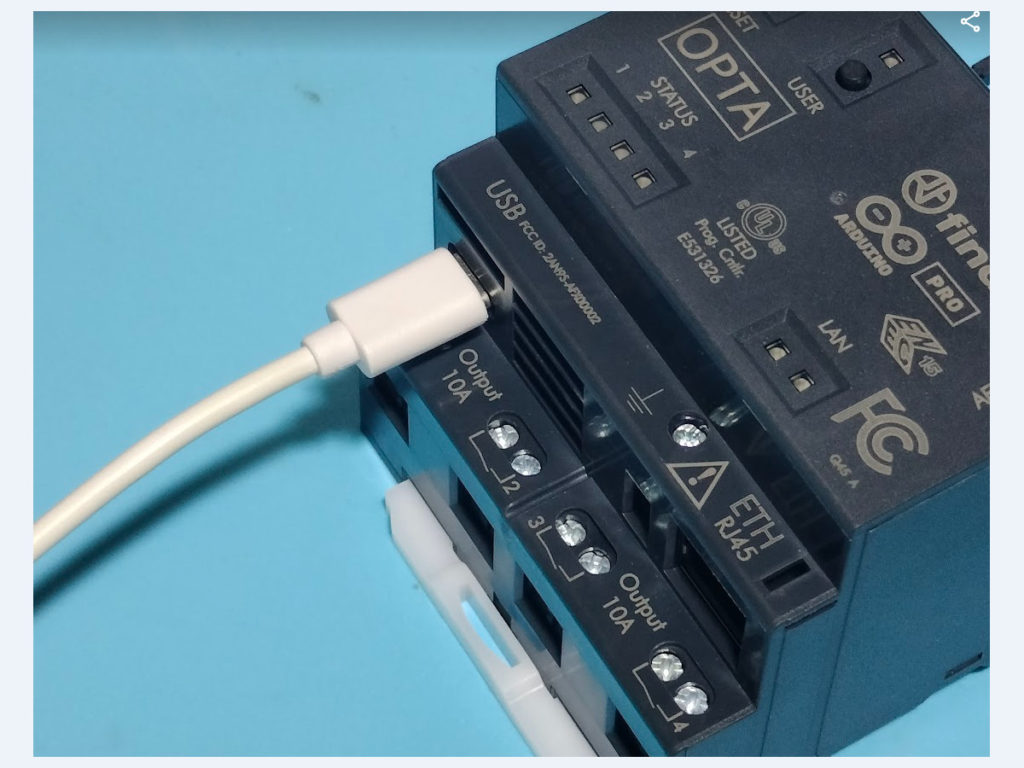
รูปที่ 6
- กลับมาที่หน้าต่างของ Arduino IDE ไปที่ Tools à board àArduino Mbed OS Opta Boardà Opta
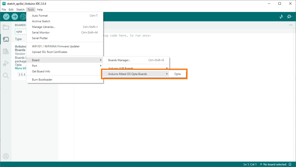
รูปที่ 7

- ส่วนการเลือกพอร์ตให้ไปที่ Tools à Port

รูปที่ 8
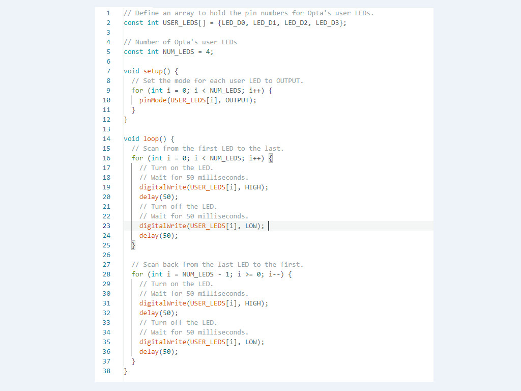
- ถึงขั้นตอนนี้ เราสามารถเริ่มต้นการเขียนโปรแกรมได้แล้ว โดยตัวอย่างโปรแกรมเป็นดังนี้
ภาพรวมของโปรแกรมจะส่งสัญญาณไปควบคุมLED ให้กะพริบในรูปแบบที่เรียกว่า Kinght Rider คือจะกะพริบแบบสแกนวนไปทั้งซ้ายและขวา ที่ตำแหน่งของ LED status ตัวอย่างโค้ด บรรทัดที่16 ถึง 25 จะสร้างการกะพริบจากตัวแรก ไปยังตัวสุดท้าย ส่วนโค้ดบรรทัดที่ 28 ถึง 37 จะสร้างการกะพริบจากท้ายกลับมายังตัวแรก วนกลับไปมาเรื่อย

รูปที่ 9