-
×
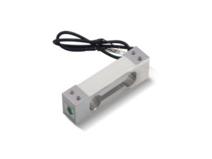 LCA001 โหลดเซลล์/สเตรนเกจ Load Cell Strain Gauge Weighing Sensor AT8500-0.3kg C3 1mV/V
 มีสินค้าอยู่ 1
1 × ฿1,120.00
รวม: ฿1,120.00
฿18,900.00
สั่งจองสินค้าได้
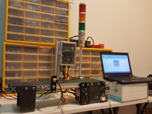
ระบบนับชิ้นงานบนสายพานลำเลียงอัตโนมัติ Conveyor Counter RS485 Sensor
เมื่องานวิ่งผ่านพร็อกซิมิตี้เซนเซอร์ ช่วยลำเลียงชิ้นงานที่นับแล้ว ไหลไปเก็บยังกล่องปลายทางสามารถนับชิ้นงานได้ มีปุ่มรีเซ็ตเป็นเมื่อต้องการเริ่มนับใหม่ สายพานลําเลียง 60X12-AC (cm) Control BOX IO + Photo Sensor ดิจิตอลเคาท์เตอร์ 6 หลักพร้อม โฟโต้เซนเซอร์ + ตั้งค่าการนับได้ ฟังก์ชั่นการเชื่อมต่อและแสดงผลบนคอมพิวเตอร์ Modbus RTU RS485
มีอะไรเตรียมไว้ให้ในชุด
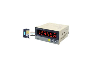
Digital Counter ดิจิตอลเคาท์เตอร์ 6 หลักความแม่นยำสูง ติดตั้งได้ง่าย เก็บตัวเลขล่าสุดค้างไว้โดยอัตโนมัติเมื่อปิดเครื่อง ใช้งานได้หลากหลาย ทั้งในระบบอัตโนมัติและการตรวจสอบ ใช้ต่อร่วมกับสายพาน เพื่อตรวจนับสินค้า
New Version 2021 Preset Digital Counter Modbus RTU + RS485
ข้อมูลด้านเทคนิค Digital Counter ดิจิตอลเคาท์เตอร์

ตัวอย่างโปรแกรม แสดงผล Counter บนคอมพิวเตอร์ Modbus RTU RS485 ด้วย Software Processing
โปรโตคอล Modbus เป็นวิธีการมาตรฐานในอุตสาหกรรมสำหรับการถ่ายโอนข้อมูล ใช้กับระบบอัตโนมัติและระบบควบคุมในงานอุตสาหกรรม
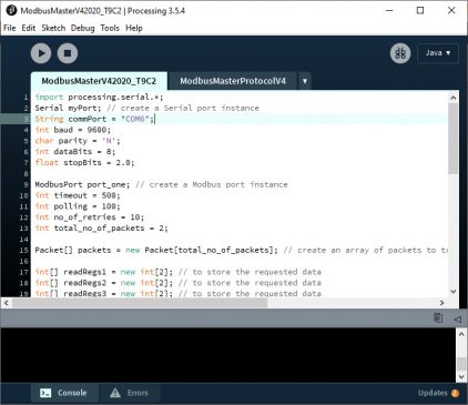
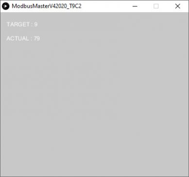
Step 5 : กดปุ่มรัน (Run) โปรแกรมจะแสดงผลค่า Target และค่าที่นับได้ (Actual)
https://photos.app.goo.gl/C5FPMGymZyZUzQi29
———————————————————————————————————————————————————————————————————————————————–
Oil Version 2020 Preset Digital Counter + Arduino USB + Excel plx-daq
|
1 2 3 4 5 6 7 8 9 10 11 12 13 14 15 16 17 18 19 20 21 22 23 24 25 26 27 28 29 30 31 32 33 34 35 36 37 38 39 40 41 42 43 44 45 46 47 48 49 50 51 52 53 54 55 56 57 58 59 60 61 62 63 64 65 66 67 68 69 70 71 72 73 74 75 76 77 78 79 80 81 82 83 84 85 86 87 88 89 90 91 92 93 94 95 96 97 |
/* Debounce Each time the input pin goes from LOW to HIGH (e.g. because of a push-button press), the output pin is toggled from LOW to HIGH or HIGH to LOW. There's a minimum delay between toggles to debounce the circuit (i.e. to ignore noise). The circuit: - LED attached from pin 13 to ground - pushbutton attached from pin 2 to +5V - 10 kilohm resistor attached from pin 2 to ground - Note: On most Arduino boards, there is already an LED on the board connected to pin 13, so you don't need any extra components for this example. created 21 Nov 2006 by David A. Mellis modified 30 Aug 2011 by Limor Fried modified 28 Dec 2012 by Mike Walters modified 30 Aug 2016 by Arturo Guadalupi This example code is in the public domain. http://www.arduino.cc/en/Tutorial/Debounce */ // constants won't change. They're used here to set pin numbers: const int buttonPin = 2; // the number of the pushbutton pin const int ledPin = 13; // the number of the LED pin // Variables will change: int ledState = HIGH; // the current state of the output pin int buttonState; // the current reading from the input pin int lastButtonState = LOW; // the previous reading from the input pin // the following variables are unsigned longs because the time, measured in // milliseconds, will quickly become a bigger number than can be stored in an int. unsigned long lastDebounceTime = 0; // the last time the output pin was toggled unsigned long debounceDelay = 50; // the debounce time; increase if the output flickers unsigned long Count = 0; unsigned long int milli_time; //variable to hold the time void setup() { pinMode(buttonPin, INPUT); pinMode(ledPin, OUTPUT); pinMode(buttonPin, INPUT_PULLUP); Serial.begin(9600); Serial.println("CLEARDATA"); Serial.println("LABEL,Computer Time,Time (Milli Sec.),Count"); // set initial LED state digitalWrite(ledPin, ledState); } void loop() { // read the state of the switch into a local variable: int reading = digitalRead(buttonPin); // check to see if you just pressed the button // (i.e. the input went from LOW to HIGH), and you've waited long enough // since the last press to ignore any noise: // If the switch changed, due to noise or pressing: if (reading != lastButtonState) { // reset the debouncing timer lastDebounceTime = millis(); } if ((millis() - lastDebounceTime) > debounceDelay) { // whatever the reading is at, it's been there for longer than the debounce // delay, so take it as the actual current state: // if the button state has changed: if (reading != buttonState) { buttonState = reading; // only toggle the LED if the new button state is HIGH if (buttonState == HIGH) { ledState = !ledState; Count++; //Serial.print(Count); //Serial.println(" pcs"); Serial.print("DATA,TIME,"); Serial.print(milli_time); Serial.print(","); Serial.println(Count); } } } // set the LED: digitalWrite(ledPin, ledState); // save the reading. Next time through the loop, it'll be the lastButtonState: lastButtonState = reading; } |
Excel plx-daq Download
ในการส่งข้อมูลแบบอนุกรมจากบอร์ด Arduino ไปยัง Excel เราจำเป็นต้องมีซอฟต์แวร์ขนาดเล็กชื่อ PLX-DAQ (เครื่องมือ Parallax Data Acquisition) ซอฟต์แวร์นี้เป็นเพียงส่วนเสริมสำหรับ Microsoft Excel ดาวน์โหลดลิงก์ PLX-DAQ
สามารถดาวน์โหลดลิงก์ PLX-DAQ ด้านล่าง:
https://www.parallax.com/package/plx-daq/
หลังจากดาวน์โหลดและติดตั้ง PLX-DAQ คุณจะเห็นโฟลเดอร์ใหม่ที่สร้างขึ้นในเดสก์ท็อปพีซีของคุณชื่อ: PLX-DAQ
ซึ่งมีไฟล์ 3 ไฟล์:
ดับเบิลคลิก (เปิดไฟล์ Excel สเปรดชีต PLX-DAQ_R2) จะมีหน้าต่างแสดงดังภาพด้านล่าง
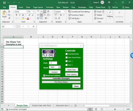
หากมีคำเตือนด้านความปลอดภัย (ปิดการใช้งานมาโคร) เพียงคลิกที่ตัวเลือก -> ตรวจสอบ: เปิดใช้งานเนื้อหานี้ -> ตกลง
*โปรดทราบว่าปลั๊กอินนี้ได้รับการทดสอบกับ Microsoft Office 2007 และควรใช้งานได้กับ Office 2010 แต่น่าเสียดายที่ไม่สามารถใช้งานกับ Office 2013 ได้
ในการเริ่มรับข้อมูล จากบอร์ด Arduino เพียงแค่เลือกพอร์ต COM และอัตราการส่งข้อมูลจากนั้นคลิกที่เชื่อมต่อ (ต้องปิดจอภาพอนุกรม Arduino IDE ก่อนเชื่อมต่อกับซอฟต์แวร์ PLX-DAQ)
เฉพาะลูกค้าที่เข้าสู่ระบบ และเคยซื้อสินค้าชิ้นนี้แล้วเท่านั้น ที่เขียนบทวิจารณ์ได้
สั่งจองสินค้าได้
หยิบใส่ตะกร้า
สั่งจองสินค้าได้
หยิบใส่ตะกร้า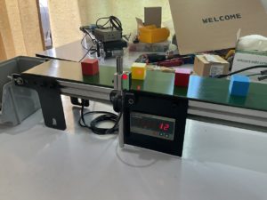
สั่งจองสินค้าได้
หยิบใส่ตะกร้า
รีวิว
ยังไม่มีบทวิจารณ์