คำอธิบาย
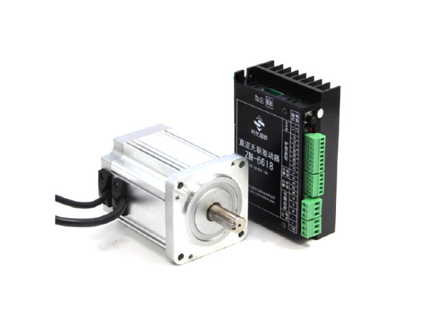
BLDC Motor with Hall Sensor
Motor Specification
- 80BLF 400W
- Rated Voltage DC48V
- Rated Current 12A
- Rated Speed 3000Rpm
- Rated Torque 1.27Nm
| Model |
Rated voltage
V |
Rated power
W |
Rated
TorqueNM |
Rated speed
rpm |
No-load speed
rpm |
Rated current
A |
No-load current
A |
Logarithm of level |
| 80BL100S40-430 |
48 |
400 |
1.27 |
3000 |
4000 |
12 |
1.2 |
2 |
|
|
|
|
|
|
|
|
|

ZM-6618M Driver Features
- Power supply voltage 20~60VDC
- Stalled rotor current 18A
- Drive mode square wave drive
- Sampling method single resistor sampling
- Speed control resistance, voltage analog control
- Parameter setting Through the debugging interface, parameters such as the number of motor pole pairs, locked rotor current, and maximum speed can be set.
- Closed-loop stable speed, the motor can still maintain speed under heavy load
- Low heat, high power, stable, reliable, high cost performance
SW1 Definition
SW1
- ON Internal speed regulation
- OFF External speed regulation Dial setting
SW2
- ON High level enable
- OFF Low level enable
Interface Definition
- V+ The control voltage is internally given, 5VDC
- VE External voltage analog input, or resistance analog input. When the resistor is input, use a 10K1% precision three-terminal resistor and use it with V and V+; when the analog voltage is given, V- is connected to the external analog ground, VE is the input, and the input range is 0~5VDC- Remember not to input beyond the range!
- V- Signal reference ground
- EN Enable the control terminal, active at low level, and the motor is offline when active. control interface
- DR Direction control terminal, when the low level is active, the motor rotates forward, and when the high level is active, the motor rotates reversely.
- BK Brake control terminal, active at low level, when active, the motor is in braking state
- ER Error output terminal, when the motor or driver has an error, the signal output is high level
- FG Speed feedback output. When the motor rotates, the signal outputs PWM with a duty cycle of 50%. The PWM frequency represents the speed, and IKHz represents 1000rpm.
Hall interface When connecting to the motor, the Hall signal lines need to be connected in a certain order. Wrong wiring, the motor cannot run
- HU Hall signal input
- HV Hall signal input
- HW Hall signal input
- H+ Hall power supply positive
- H- Hall power supply negative
Motor output At the motor wire access end, the colors of the three motor wires and the Hall signal wire must match. If the colors do not match, it means that the power
The machine line is wrong and the motor cannot run.
Power input The driver is a DC voltage input, please note that the polarity of the power supply cannot be connected incorrectly.
ในชุดประกอบด้วย
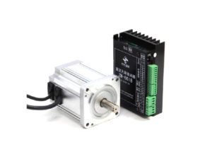
- 1x มอเตอร์บัสเลส 80mm BLDC Motor DC48V/400W 80BL400
- 1x ZM-6618M Driver
เฉพาะลูกค้าที่เข้าสู่ระบบ และเคยซื้อสินค้าชิ้นนี้แล้วเท่านั้น ที่เขียนบทวิจารณ์ได้
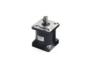 GM0201 เกียร์มอเตอร์ 57mm Nema23 Stepper Motor Planetary Gearbox 57PX10 Stage 1
 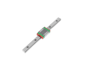 LBM314 บล็อครางสไลด์ Linear Guide Ball Bearing Slide Block MGN12H+MGR12-250




รีวิว
ยังไม่มีบทวิจารณ์