1. การคำนวณอุณหภูมิ
สมการหา อุณหภูมิ (℃) = (TV – V0) / Vr * Tr + T0
เมื่อ
ตัวอย่างการคำนวณ
2. การคำนวณ Humidity
สมการหา Humidity (%RH) = (HV – V0) / Vr*Hr + H0
ตัวอย่างการคำนวณ
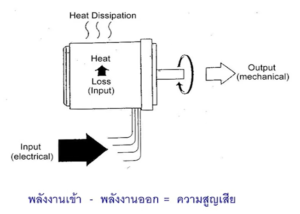
แรงดันไฟฟ้าขาออกสูงสุดคือไม่เกินแรงดันไฟฟ้าของแหล่งจ่ายไฟ -2V เพื่อให้ได้เอาต์พุต 10V ที่อุณหภูมิสูงหรือความชื้นสูงแนะนำให้จ่ายไฟอย่างน้อย 12V
หน่วยแรงบิดที่ใช้กันทั่วไป:
1 nm = 10 kg.cm = 0.1 kg.m
แรงบิดมาตรฐานของมอเตอร์คือ 10 kg.cm สมมติว่าใช้รอกในการหมุน รัศมีของรอกคือ 1 cm.
ความตึงของสายพานคือ 10 kg ถ้ารัศมีของรอกคือ 2 cm. ความตึงของสายพานจะเท่ากับ 5 kg.
แนวคิดเกี่ยวกับแรงบิด:
ตัวอย่างเช่น: การยกถัง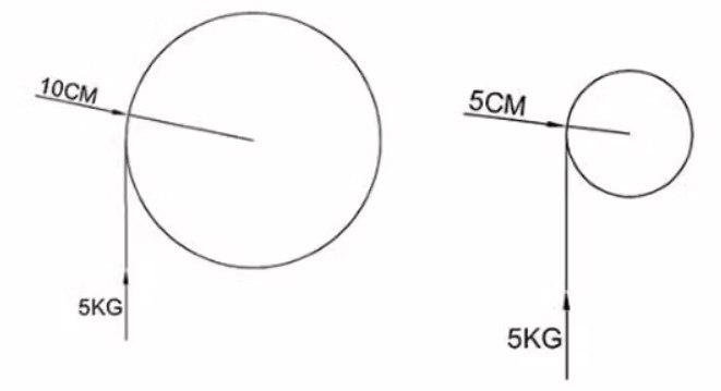
ภาพด้านซ้าย
ภาพด้านขวา
จากตัวอย่างนี้ จะเห็นได้ว่า แกนยื่น มีความสำคัญมาก และแรงบิดในการยกที่น้ำหนักเท่ากันนั้นแตกต่างกัน
สายพานไทมิ่ง (Timing Belt) เป็นสายพานที่ใช้งานในระบบเครื่องยนต์ สายพานไทมิ่งเบอร์ XL มีขนาดระยะพิทช์ (pitch) เท่ากับ 5.08mm.
การแปลงสายพานไทม์มิ่งเบอร์ XL เป็นความยาวรอบวงของสายพาน
L = (XL/2)xP
โดยที่
ตัวอย่างเช่น หากต้องการแปลงสายพานไทม์มิ่งเบอร์ 100XL หรือ XL100 เป็นความยาวรอบวง หน่วย mm.
L = (100/2)x5.08
ความยาวรอบวงพานไทม์มิ่งเบอร์ 100XL หรือ XL100 = 254 mm.
ในการแปลงนิวตัน-เมตร (N-m) เป็นกิโลกรัม-เซนติเมตร (กก.-ซม.) สามารถใช้ การแปลงต่อไปนี้:
1 N-m = 100 kg-cm
ดังนั้น หากต้องการแปลงค่าจาก N-m เป็น kg-cm ให้คูณค่าด้วย 100
ตัวอย่างเช่น ถ้ามีค่าแรงบิด 20 N-m เราสามารถแปลงเป็น kg-cm ได้ดังนี้:
20 N-m * 100 kg-cm/N-m = 2000 kg-cm
ดังนั้น 20 N-m เท่ากับ 2,000 kg-cm
หลักการควบคุมไดรเวอร์มอเตอร์ L298 ด้วย Arduino และสมาร์ทโฟน จะต้องตั้งค่าการสื่อสาร Bluetooth ระหว่าง Arduino และสมาร์ทโฟน ติดตั้งโมดูล Bluetooth เช่น Bluetooth HC-05 (ZS-040) บน Arduino และต่อสายตามแผ่นข้อมูลของโมดูล ส่งคำสั่งจากสมาร์ทโฟนไปยัง Arduino เพื่อควบคุม L298 และมอเตอร์ที่เชื่อมต่ออยู่ ตัวอย่างเช่น ส่ง “F” เพื่อให้มอเตอร์เคลื่อนที่ไปข้างหน้า ส่ง “B” เพื่อให้มอเตอร์เคลื่อนที่ถอยหลัง และ ส่ง “S” เพื่อหยุดมอเตอร์ สามารถส่งคำสั่งเพื่อควบคุมความเร็วของมอเตอร์ เช่น “1” สำหรับความเร็วต่ำและ “9” สำหรับความเร็วสูง
รวบรวมวัสดุที่จำเป็น:
แผนผังการต่อสายไฟ
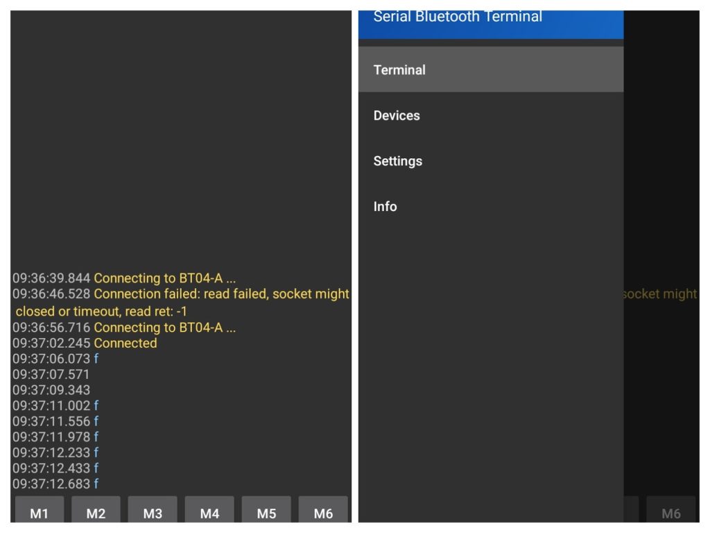
ติดตั้งแอพเทอร์มินัล Bluetooth บนสมาร์ทโฟน
แอพ Android และ iOS ที่ให้เราส่งและรับข้อมูลผ่านบลูทูธ โดยใช้ Bluetooth terminal app, Serial Bluetooth Terminal, Bluetooth Terminal
ตั้งค่าฮาร์ดแวร์:
เชื่อมต่อโมดูลบลูทูธ เข้ากับ Arduino
เขียน Code: arduino
เขียน Sketch สำหรับ Arduino เพื่อควบคุม L298 ตามคำสั่งที่ได้รับผ่านการเชื่อมต่อ Bluetooth Sketch นี้ใช้ไลบรารี software serial เพื่อตั้งค่าพอร์ตอนุกรมที่สองสำหรับ Bluetooth Module และรับฟังคำสั่งผ่านพอร์ตนี้ในฟังก์ชันลูป เมื่อได้รับคำสั่ง มันจะควบคุม L298 ตามอักขระที่ได้รับ L298 ถูกควบคุมโดยใช้ฟังก์ชันเอาต์พุตดิจิตอลเพื่อกำหนดทิศทางของมอเตอร์ และฟังก์ชันเอาต์พุตแบบอะนาล็อกเพื่อตั้งค่าความเร็วของมอเตอร์โดยใช้การมอดูเลตความกว้างพัลส์ (PWM)
#include <SoftwareSerial.h>

// Set up a software serial port for the HC-05, HC-06 Bluetooth module
SoftwareSerial BTserial(10, 11); // RX, TX

// Set up constants for the L298 control pins
const int in1 = 4; // MOTOR1 DIR
const int in2 = 5; // MOTOR1 DIR
const int enA = 6; // MOTOR1 SPEED

const int in3 = 7; // MOTOR2 DIR
const int in4 = 8; // MOTOR2 DIR
const int enB = 9; // MOTOR2 SPEED

void setup() {
  // Initialize serial communication with the computer
  Serial.begin(9600);
  // Initialize serial communication with the HC-05
  BTserial.begin(9600);

  // Set up the L298 control pins as outputs
  pinMode(enA, OUTPUT);
  pinMode(in1, OUTPUT);
  pinMode(in2, OUTPUT);
  pinMode(enB, OUTPUT);
  pinMode(in3, OUTPUT);
  pinMode(in4, OUTPUT);
}

void loop() {
  // Check if there is data available from the HC-05
  if (BTserial.available()) {
    // Read a single character from the HC-05
    char c = BTserial.read();
            Serial.print(c);

    // Check the character and control the L298 accordingly
    switch (c) {
      case 'f':
  // Forward
  digitalWrite(in1, HIGH);
  digitalWrite(in2, LOW);
  digitalWrite(in3, HIGH);
  digitalWrite(in4, LOW);
  analogWrite(enA, 255); // Full speed
  analogWrite(enB, 255); // Full speed
        break;

      case 'b':
  // Backward
  digitalWrite(in1, LOW);
  digitalWrite(in2, HIGH);
  digitalWrite(in3, LOW);
  digitalWrite(in4, HIGH);
  analogWrite(enA, 255); // Full speed
  analogWrite(enB, 255); // Full speed
        break;

      case 's':
  // Stop
  digitalWrite(in1, LOW);
  digitalWrite(in2, LOW);
  digitalWrite(in3, LOW);
  digitalWrite(in4, LOW);
  analogWrite(enA, 0); // 0% duty cycle
  analogWrite(enB, 0); // 0% duty cycle
        break;

      case '1':
        // Low speed
        analogWrite(enA, 128); // 50% duty cycle
        analogWrite(enB, 128); // 50% duty cycle
        break;

      case '9':
        // High speed
        analogWrite(enA, 255); // 100% duty cycle
        analogWrite(enB, 255); // 100% duty cycle
        break;

      default:
        // Invalid command
        break;
    }
  }
}
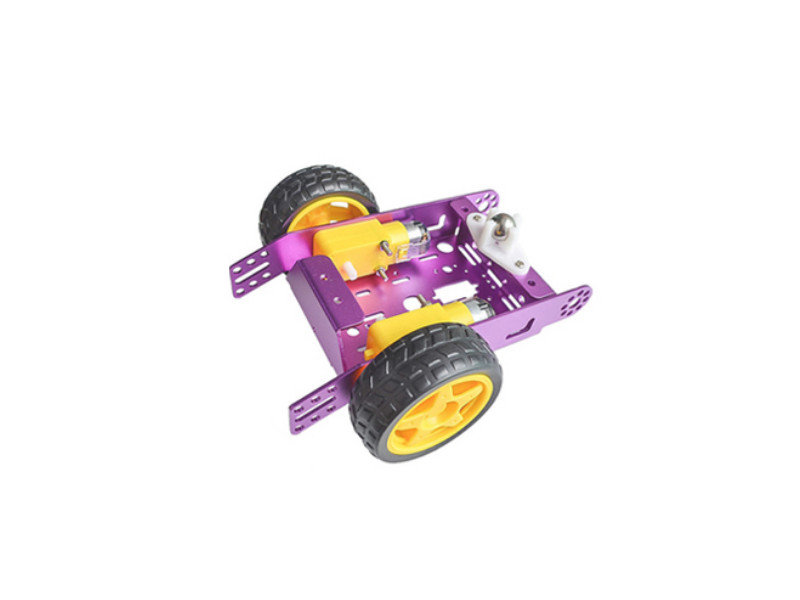
ในการควบคุมรถ RC โดยใช้ Arduino และไดรเวอร์มอเตอร์ L298N จะต้องทำตามขั้นตอนเหล่านี้
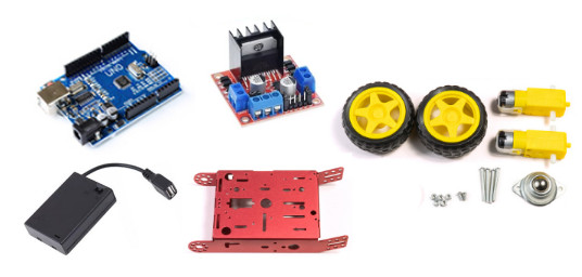
รวบรวมวัสดุที่จำเป็น:
ตั้งค่าฮาร์ดแวร์:
แผนผังการต่อสายไฟ
https://oshwlab.com/s2insupply/arduino-l298n-rc-robot-car
เขียน Code: arduino
// Set up constants for the L298 control pins
const int in1 = 4; // MOTOR1 DIR
const int in2 = 5; // MOTOR1 DIR
const int enA = 6; // MOTOR1 SPEED

const int in3 = 7; // MOTOR2 DIR
const int in4 = 8; // MOTOR2 DIR
const int enB = 9; // MOTOR2 SPEED

void setup() {
  // Set up the L298 control pins as outputs
  pinMode(in1, OUTPUT);
  pinMode(in2, OUTPUT);
  pinMode(enA, OUTPUT);

  pinMode(in3, OUTPUT);
  pinMode(in4, OUTPUT);
  pinMode(enB, OUTPUT);
}

void loop() {
  // Forward
  digitalWrite(in1, HIGH);
  digitalWrite(in2, LOW);
  analogWrite(enA, 255); // Full speed
  digitalWrite(in3, HIGH);
  digitalWrite(in4, LOW);
  analogWrite(enB, 255); // Full speed

  // Wait for 1 second
  delay(1000);

  // Backward
  digitalWrite(in1, LOW);
  digitalWrite(in2, HIGH);
  analogWrite(enA, 255); // Full speed
  digitalWrite(in3, LOW);
  digitalWrite(in4, HIGH);
  analogWrite(enB, 255); // Full speed

  // Wait for 1 second
  delay(1000);
  // Stop
  digitalWrite(in1, LOW);
  digitalWrite(in2, LOW);
  digitalWrite(in3, LOW);
  digitalWrite(in4, LOW);
  analogWrite(enA, 0); // 0% duty cycle
  analogWrite(enB, 0); // 0% duty cycle

  // Wait for 1 second
  delay(1000);
}
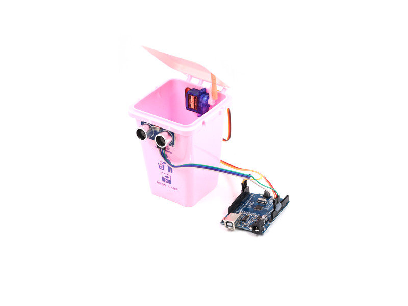
ภาพรวมของระบบถังขยะควบคุมอัตโนมัติประกอบด้วยส่วนประกอบหลัก 3 ส่วนได้แก่ตัวควบคุมเซ็นเซอร์และมอเตอร์ควบคุมในที่นี้ส่วน input ให้มาจากเซ็นเซอร์เซ็นเซอร์อัลตร้าโซนิคและ output ที่สามารถควบคุมการเคลื่อนไหวนั่นคือมอเตอร์ขนาดเล็กนั่นเอง
วิธีทำถังขยะอัตโนมัติโดยใช้อาดูโน่และเซอร์โวมอเตอร์และอัลตร้าโซนิคเซนเซอร์ การทำถังขยะอัตโนมัติโดยใช้ Arduino เซอร์โวมอเตอร์ และเซ็นเซอร์อัลตราโซนิกเป็นโครงการง่ายๆ ที่สามารถทำได้ในไม่กี่ขั้นตอน นี่คือโครงร่างทั่วไปของวิธีเริ่มต้นใช้งาน: หลักการทำงานของ เซ็นเซอร์อัลตราโซนิก HC-SR04 เป็นอุปกรณ์ยอดนิยมและราคาไม่แพงที่สามารถใช้วัดระยะทางไปยังวัตถุได้ ทำงานโดยปล่อยคลื่นเสียงความถี่สูงและวัดเวลาที่คลื่นเสียงสะท้อนกลับหลังจากกระทบวัตถุ หากต้องการใช้เซ็นเซอร์อัลตราโซนิก HC-SR04 กับบอร์ด Arduino จะต้องเชื่อมต่อเข้ากับบอร์ดโดยใช้สายจัมเปอร์ HC-SR04 มี 4 พิน คือ Vcc, Trig, Echo และ GND
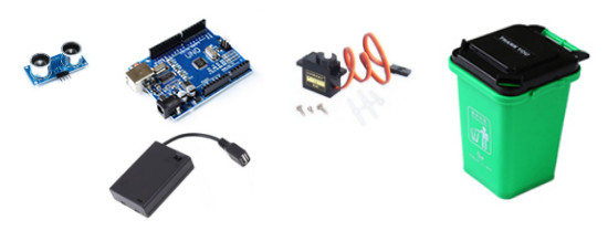
รวบรวมวัสดุที่จำเป็น:
ตั้งค่าฮาร์ดแวร์:
How HC-SR04 Ultrasonic Module Distance Sensor works
เซ็นเซอร์จะส่ง Ping ที่เวลา t1 และรับการ Ping ที่เด้งที่เวลา t2 เมื่อทราบความเร็วของเสียง ความแตกต่างของเวลา Δt = t2 – t1 สามารถทำให้เราทราบระยะทางของวัตถุได้
ตัวอย่างเช่น ถ้า Δt = 500us เรารู้ว่าต้องใช้เวลา 250us ในการส่ง Ping ไปกระทบวัตถุ และอีก 250us ในการกลับมา
ความเร็วเสียง c โดยประมาณในอากาศแห้งกำหนดโดย สมการ:
ระยะทางคือ
หรือ
แทนที่จะใช้ความเร็วของเสียง เราสามารถใช้ “อัตราเร็วของเสียง” ได้เช่นกัน
อัตราเร็วของเสียง = 1 / c
อัตราเร็วของเสียง = 1 / 0.03435
อัตราเร็วของเสียง = 29.1ss/cm
ในกรณีนี้ สมการที่ใช้คำนวณระยะทางจะกลายเป็น:
และสำหรับตัวอย่างด้านบน:
https://www.instructables.com/Using-a-SR04/
แผนผังการต่อสายไฟ
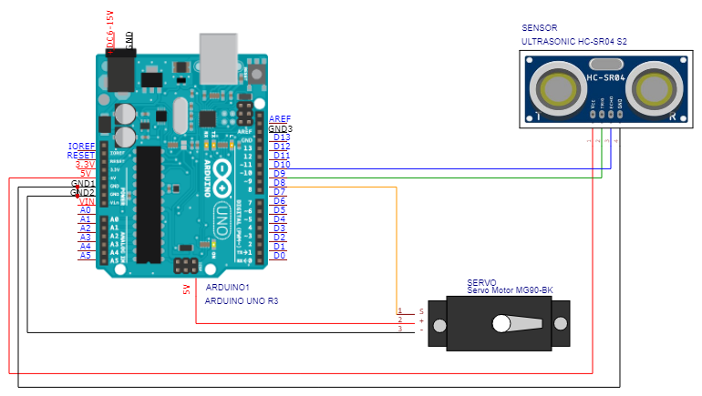
https://oshwlab.com/s2insupply/arduino-automatic-waste-bin
เขียน Code: arduino Code เชื่อมต่ออัลตราโซนิคเซนเซอร์เพื่อควบคุมเซอร์โวมอเตอร์
ตัวอย่าง Arduino Code เชื่อมต่ออัลตราโซนิคเซนเซอร์เพื่อวัดระยะทางไปยังวัตถุ
// define the pins for Ultrasonic Sensor HC-SR04
const int trigPin = 9;  // define the trigPin and trigPin for the Ultrasonic Sensor HC-SR04
const int echoPin = 10; // define the trigPin and echoPin for the Ultrasonic Sensor HC-SR04

void setup() {
  // initialize the pins as outputs and inputs
  pinMode(trigPin, OUTPUT);
  pinMode(echoPin, INPUT);

  // start the serial communication
  Serial.begin(9600);
}

void loop() {
  // send a pulse to the trigPin
  digitalWrite(trigPin, HIGH);
  delayMicroseconds(10);
  digitalWrite(trigPin, LOW);

  // measure the time it takes for the pulse to return
  long duration = pulseIn(echoPin, HIGH);

  // calculate the distance based on the speed of sound
  int distance = duration * 0.034 / 2;

  // print the distance to the serial monitor
  Serial.println(distance);

  // wait a bit before taking the next measurement
  delay(100);
}
ตัวอย่าง Arduino Code เชื่อมต่ออัลตราโซนิคเซนเซอร์เพื่อวัดระยะทางไปยังวัตถุและควบคุมเซอร์โวมอเตอร์
#include <Servo.h> // include the Servo library

Servo myservo; // create a servo object

// define the pins for Ultrasonic Sensor HC-SR04
const int trigPin = 9;  // define the trigPin and trigPin for the Ultrasonic Sensor HC-SR04
const int echoPin = 10; // define the trigPin and echoPin for the Ultrasonic Sensor HC-SR04

void setup() {
  myservo.attach(8); // attach the servo to pin 8
  pinMode(trigPin, OUTPUT); // set the trigPin as an output
  pinMode(echoPin, INPUT); // set the echoPin as an input

  // start the serial communication
  Serial.begin(9600);

}

void loop() {
  long duration, distance; // create variables to store the duration and distance

  digitalWrite(trigPin, LOW); // set the trigPin low
  delayMicroseconds(2); // wait for 2 microseconds

  digitalWrite(trigPin, HIGH); // set the trigPin high
  delayMicroseconds(10); // wait for 10 microseconds

  digitalWrite(trigPin, LOW); // set the trigPin low

  duration = pulseIn(echoPin, HIGH); // read the duration of the pulse
  distance = (duration/2) / 29.1; // calculate the distance in centimeters

  if (distance < 20) { // if the distance is less than 20 cm
    myservo.write(0); // set the servo to 0 degrees
    delay(1000); // wait for 1 second
    myservo.write(90); // set the servo to 90 degrees
  }
  else { // if the distance is greater than 20 cm
    myservo.write(90); // set the servo to 90 degrees
        Serial.println(distance);
  }
}
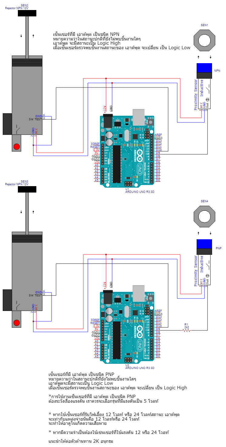
เซ็นเซอร์ที่มี เอาต์พุต เป็นชนิด NPN
หมายความว่าในสถานะปกติที่ยังไม่พบชิ้นงานใดๆ
เอาต์พุต จะมีสถานะเป็น Logic High
เมื่อเซ็นเซอร์ตรวจพบชิ้นงานสถานะของ เอาต์พุต จะเปลี่ยน เป็น Logic Low
เราสามารถประโยช์การเปลี่ยนแปลงสัญยาณเอาต์พุตของเซ็นเซอร์ เอาไปใช้ในการควบคุมอุปกรณ์ เอาต์พุต อย่างเช่น Rejector ได้
เซ็นเซอร์ที่มี เอาต์พุต เป็นชนิด PNP
หมายความว่าในสถานะปกติที่ยังไม่พบชิ้นงานใดๆ
เอาต์พุตจะมีสถานะเป็น Logic Low
เมื่อเซ็นเซอร์ตรวจพบชิ้นงานสถานะของ เอาต์พุต จะเปลี่ยน เป็น Logic High
*การใช้งานเซ็นเซอร์ที่มี เอาต์พุต เป็นชนิด PNP
ต้องระวังเรื่องแรงดัน เราควรจะเลือกรุ่นที่มีแรงดันเป็น 5 โวลท์
* หากใช้เซ็นเซอร์ที่รับไฟเลี้ยง 12 โวลท์ หรือ 24 โวลท์สถานะ เอาต์พุต
จะเท่ากับแหล่งจ่ายนั่นคือ 12 โวลท์หรือ 24 โวลท์
จะทำให้อาดูโน่เกิดความเสียหาย
* หากมีความจำเป็นต้องใช้เซนเซอร์ที่ใช้แรงดัน 12 หรือ 24 โวลท์
แนะนำให้ต่อตัวต้านทาน 2K อนุกรม

เอกสารทดสอบบาร์โค้ด Barcode QR Code test sheet
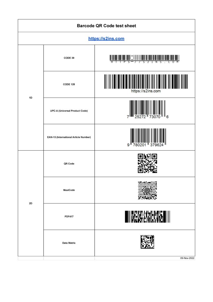
https://docs.google.com/spreadsheets/d/1zfXAqGIVnsNyaUxaVgUlXObJ1HduWZ5xbvK48wJVpTE/edit?usp=sharing