คำอธิบาย
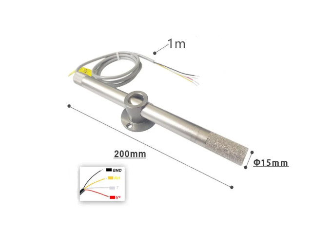
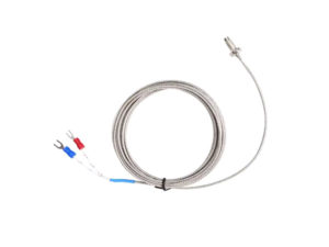
ไปป์ไลน์โพรบ เซนเซอร์วัดอุณหภูมิและความชื้น เครื่องส่งสัญญาณอุณหภูมิและความชื้นนี้ใช้ ในระบบ HVAC เครื่องลดความชื้น อุปกรณ์ทดสอบและตรวจสอบ สินค้าอุปโภคบริโภค ยานยนต์ ระบบควบคุมอัตโนมัติ เครื่องบันทึกข้อมูล สถานีตรวจอากาศ เครื่องใช้ในบ้าน การควบคุมอุณหภูมิ Temperature and Humidity Transmitter Pipeline Probe CJ6
สเปกสินค้า (Specifications)
- CJ6485
- Working voltage DC12~36V
- Output Digital Digital Output RS485 Modbus RTU
- Power-on time 3S
- Shell material aluminum alloy Probe Type: Pipeline Probe (สำหรับดูดอากาศผ่านท่อ/หลักท่อ)
- Device power consumption 10mA
- สาย 24AWG 4Core ยาว 90 cm
- อลูมิเนียมอัลลอยด์ออกซิไดซ์และอิเล็กโทรไลต์ กันฝุ่น ทนอุณหภูมิสูง ไม่นำไฟฟ้า ทำความสะอาดง่าย กันฝุ่น ยืดอายุของเซ็นเซอร์

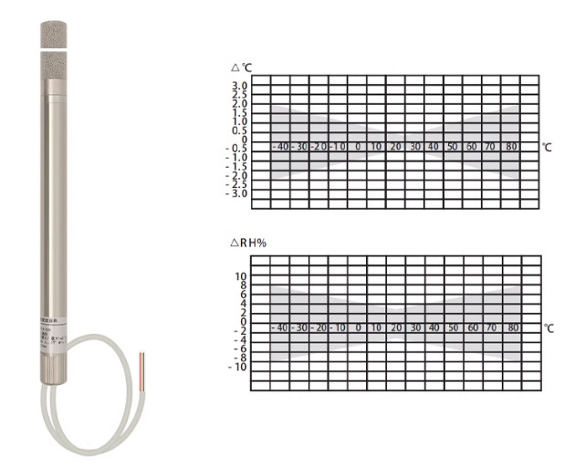
Temperature
- ช่วงการวัด Measurement Temperature range -40~120℃
- Accuracy +0.3℃
- Resolution 0.1℃
Humidity
- ช่วงการวัด Measurement Humidity range 0~99.9% non-condensing
- Accuracy +3%RH
- Resolution 0.1%RH
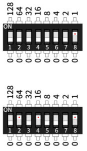
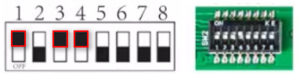
การตั้งค่า Address Dip Switch – Address Setting
- 0-254 (Default 01 Address)
วิธีตั้ง Address ของ CJ6485
- DIP Switch 1–8 มีค่าน้ำหนักดังนี้:
การเลือกที่อยู่ DIP Address
- DIP สวิตช์ เทียบเท่ากับเลขฐานสอง 8 บิต (7-0) โดยบิตสูงอยู่ทางซ้ายและบิตต่ำอยู่ทางขวา การหมุนขึ้นเป็น ON หมายความว่าบิตเป็น 1 และการหมุนลงเป็น 0. ที่อยู่ Address จริงจะเท่ากับผลรวมของค่าของแต่ละบิต ดังนั้นจึงสามารถตั้งค่าที่อยู่ Address ได้ทั้งหมด 255 รายการตั้งแต่ 1 ถึง 255 (ค่าเริ่มต้นคือ 1)
- ผลลัพธ์ที่แสดงในรูปที่ 1 คือ = 0+0+0+0+0+0+0+0+1 = 1
- ดังนั้น Address ที่แสดง คือ “1”
ผลลัพธ์ที่แสดงในรูป คือ 0+64+0+16+0+0+0+1 = 81 ดังนั้น Address ที่แสดง คือ “81”
| Switch | ค่า Address |
|---|---|
| 1 | 1 |
| 2 | 2 |
| 3 | 4 |
| 4 | 8 |
| 5 | 16 |
| 6 | 32 |
| 7 | 64 |
| 8 | 128 |
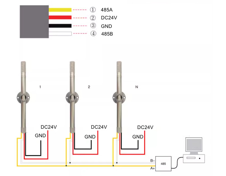
Pinout to PLC
- สายสีแดง Red ไฟเลี้ยง DC12~36V
- สายสีเหลือง Yellow RS485 A
- สายสีดำ Black GND
- สายสีขาว White RS485 B
Dimension

ในชุดประกอบด้วย
- 1 pcs x Temperature Humidity Sensor
- 2 pcs x Screw
- 2 pcs x Wall Plug
- 1 pcs x Pin Ejector
- 2 pcs x Accessory

1. ModBus Communication Protocol
- ค่าเริ่มต้นของอุปกรณ์คือ 9600, 8, N, 1
- Data bit 8, stop bit 1, no parity, no handshake
ฟังก์ชันโค้ดที่รองรับ
- 0x03 → อ่านหลายรีจิสเตอร์ (Read Holding Registers)
- 0x10 → เขียนหลายรีจิสเตอร์ (Write Multiple Registers)
2. คำสั่ง Instruction
คำสั่งอ่าน (Read Instruction)
รูปแบบเฟรมที่โฮสต์ (Master) ส่งออกไป
[ที่อยู่อุปกรณ์] + 0x03 + [ที่อยู่เริ่มต้นของรีจิสเตอร์ 2 ไบต์] + [จำนวนรีจิสเตอร์ 2 ไบต์] + [CRC ต่ำ] + [CRC สูง]
รูปแบบเฟรมที่อุปกรณ์ตอบกลับ
[ที่อยู่อุปกรณ์] + 0x03 + [จำนวนไบต์ที่ส่งกลับ 1 ไบต์] + [ข้อมูล Data 0 ~ n] + [CRC ต่ำ] + [CRC สูง]
คำสั่งเขียน (Write Instruction)
รูปแบบเฟรมที่โฮสต์ส่ง
[ที่อยู่อุปกรณ์] + 0x10 + [ที่อยู่เริ่มต้นของรีจิสเตอร์ 2 ไบต์] +

[จำนวนรีจิสเตอร์ 2 ไบต์] + [จำนวนไบต์ข้อมูล 1 ไบต์] +

[ข้อมูล Data 0 ~ n] + [CRC ต่ำ] + [CRC สูง]
รูปแบบเฟรมที่เซนเซอร์ตอบกลับ (Sensor Return Format)
Host frame format
- Sensor address + 0x03 + register starting address (2 bytes) + number of registers (2 bytes) + CRC low + CRC high
- Sensor address + 0x10 + register starting address (2 bytes) + number of registers (2 bytes) + send bytes + data 0 +…+ Data n + CRC low + CRC high
Sensor return format
- Sensor address + 0x03 + return bytes + data 0 +…+ Data n + CRC low + CRC high
- Sensor address + 0x10 + register starting address (2 bytes) + number of registers (2 bytes) + CRC low + CRC high
Example 1
อ่านค่าอุณหภูมิและความชื้น (Master ส่ง):01 03 00 00 00 02 C4 0B
ค่าที่ Slave ตอบ (Return value):01 03 04 02 C8 01 0D BA 20
ความหมายทีละไบต์
01= ที่อยู่ Slave03= Function Code (Read Holding Registers)04= จำนวนไบต์ข้อมูลถัดไป (4 ไบต์ = 2 รีจิสเตอร์)02 C8= ค่าความชื้น (Humidity) – จัดเก็บแบบ Big-endian: High→Low01 0D= ค่าอุณหภูมิ (Temperature) – จัดเก็บแบบ Big-endian: High→LowBA 20= CRC16 (ลำดับส่ง Low→High) ⇒ CRC ที่คำนวณได้คือ 0x20BA
การแปลงค่า (เอกสารรุ่นนี้ใช้สเกล ×10 → ต้อง “หาร 10” เพื่อได้ค่าจริง)
02 C8(hex) = 0x02C8 = 712(10) → 71.2 %RH01 0D(hex) = 0x010D = 269(10) → 26.9 °C
Example 2
เฟรมที่โฮสต์ส่ง:01 03 00 00 00 02 C4 0B
โฮสต์ส่งคำสั่ง อ่านรีจิสเตอร์ ไปที่อุปกรณ์ Modbus-RTU
อ่านจาก ที่อยู่เริ่มต้น 0x0000 จำนวน 2 รีจิสเตอร์ (เช่น ความชื้น + อุณหภูมิ) พร้อม CRC กำกับ
ความหมายทีละไบต์
01= Slave Address = 103= Function Code 0x03 (Read Holding Registers)00 00= Start Address = 0x000000 02= จำนวนรีจิสเตอร์ที่จะอ่าน (Quantity = 2)C4 0B= CRC16 (ลำดับ Low→High ตาม Modbus RTU)
Slave ส่งกลับ: 01 03 04 01 D7 00 D6 CA 69
ความหมายทีละไบต์
01= Slave Address = 103= Function Code = Read Holding Registers04= จำนวนไบต์ข้อมูลที่ตามมา = 4 ไบต์ (หมายถึง 2 รีจิสเตอร์ × 2 ไบต์)01 D7= รีจิสเตอร์ที่ 0 (ความชื้น)- High byte =
01 - Low byte =
D7
- High byte =
-
00 D6= รีจิสเตอร์ที่ 1 (อุณหภูมิ)- High byte =
00 - Low byte =
D6
- High byte =
-
CA 69= CRC16 (ลำดับส่ง Low→High ตาม Modbus: Low=CA, High=69)
แปลงค่าดิบเป็นค่าจริง (ตามสเกล ×10)
กำหนดให้ หาร 10 เพื่อได้ค่าจริง
- ความชื้น:
0x01D7= 471(10) → 47.1 %RH - อุณหภูมิ:
0x00D6= 214(10) → 21.4 °C
การแมปตำแหน่งภายในของรีจิสเตอร์ (ตั้งแต่ที่อยู่ 0x0000 ถึง 0x001F ไม่รวมส่วนบันทึกที่อยู่ของตัวส่งสัญญาณ)
- อุปกรณ์มี Internal Register อยู่ช่วง 0x0000 – 0x001F แต่ ไม่รวม รีจิสเตอร์ที่เกี่ยวกับ “Transmitter Address” (ที่อยู่ของตัวอุปกรณ์)
- รีจิสเตอร์ชุดนี้ใช้สำหรับ อ่านค่า, อ่านรุ่นอุปกรณ์, อ่าน/เขียนค่าเตือน, อ่าน serial, และ เขียน offset ค่าชดเชย
ตารางรีจิสเตอร์ช่วง 0x0000 – 0x001F
| Address | รายการ (Function) | อ่าน/เขียน |
|---|---|---|
| 0x0000 | ความชื้น (Humidity) | Read |
| 0x0001 | อุณหภูมิ (Temperature) | Read |
| 0x0002 – 0x0003 | Reserved | — |
| 0x0004 – 0x0007 | Reserved | — |
| 0x0008 | รุ่นอุปกรณ์ (Device Model) | Read |
| 0x0009 | เวอร์ชัน (Version Low 8-bit) | Read |
| 0x000A – 0x000B | Device ID (High/Low 16-bit) | Read |
| 0x000C | Temperature upper limit | Write |
| 0x000D | Temperature upper enable | Write |
| 0x000E | Temperature lower limit | Write |
| 0x000F | Temperature lower enable | Write |
| 0x0010 | Humidity upper limit | Write |
| 0x0011 | Humidity upper enable | Write |
| 0x0012 | Humidity lower limit | Write |
| 0x0013 | Humidity lower enable | Write |
| 0x0014 – 0x0015 | Reserved | — |
| 0x0016 | Temperature calibration update | Write |
| 0x0017 | Humidity calibration update | Write |
| 0x0018 – 0x001F | Reserved | — |
หมายเหตุสำคัญ
- เขียนได้เฉพาะ 0x000C – 0x001E
- ถ้าเขียนค่าผิดช่วง → อุปกรณ์ ไม่อัปเดต
- ถ้าเกินขอบเขต → อุปกรณ์จะ บังคับให้เป็นค่าขอบเขต
- ทุกค่าที่เป็นตัวเลขแบบมีทศนิยม ต้อง คูณ 10 ก่อนเขียน
| Parameter | Address | Parameter | Address | Parameter | Address | Parameter | Address |
| ความชื้น (Humidity) | 0x0000 | Upper temperature limit alarm value | 0x000C | continue to have | 0x0018 | Time modification enables | 0x0024 |
| อุณหภูมิ (Temperature) | 0x0001 | Upper temperature alarm enables | 0x000D | continue to have | 0x0019 | Year | 0x0025 |
| Upper temperature limit alarm sign | 0x0002 | Lower limit of temperature alarm value | 0x000E | continue to have | 0x001A | Month | 0x0026 |
| Lower limit of temperature, the alarm mark | 0x0003 | Lower temperature alarm is enabled | 0x000F | continue to have | 0x001B | Day | 0x0027 |
| High limit limit alarm mark | 0x0004 | Upper humidity limit alarm value | 0x0010 | continue to have | 0x001C | Hrs | 0x0028 |
| Lower limit of humidity alarm sign | 0x0005 | High humidity limit alarm is enabled | 0x0011 | Temperature correction positive is updated | 0x001D | Minute | 0x0029 |
| continue to have | 0x0006 | Lower humidity limit alarm value | 0x0012 | Humidity calibration positive value update | 0x001E | second | 0x002A |
| continue to have | 0x0007 | Lower humidity limit alarm enables | 0x0013 | Alarm recording cycle | 0x001F | continue to have | 0x002B |
| รุ่นอุปกรณ์ (Device Model) | 0x0008 | continue to have | 0x0014 | Normal recording cycle | 0x0020 | continue to have | 0x002C |
| เวอร์ชัน (Version Low 8-bit) | 0x0009 | continue to have | 0x0015 | Record the switch | 0x0021 | continue to have | 0x002D |
| Device ID is 16 bits high | 0x000A | continue to have | 0x0016 | Number of points recorded | 0x0022 | continue to have | 0x002E |
| Device ID is 16 bits lower | 0x000B | continue to have | 0x0017 | Record zero | 0x0023 |
3. รหัสข้อผิดพลาด (Error Code)
- 0x81 — ฟังก์ชันโค้ดไม่ถูกต้อง (อุปกรณ์ไม่รองรับฟังก์ชันโค้ดที่ส่งมา)
- 0x82 — อ่านที่อยู่รีจิสเตอร์ผิด (ที่อยู่รีจิสเตอร์ไม่ถูกต้อง หรืออยู่นอกช่วงที่อนุญาต)
- 0x83 — เขียนข้อมูลไม่ถูกต้อง (พยายามเขียนรีจิสเตอร์ที่เขียนไม่ได้ หรืออุปกรณ์ไม่อนุญาตให้เขียน)
4. วิธีคำนวณ CRC
- สร้างรีจิสเตอร์ขนาด 16 บิต เรียกว่า CRC Register และกำหนดค่าเริ่มต้นเป็น
FFFFh - นำข้อมูลไบต์แรกของเฟรมมา XOR กับไบต์ต่ำของ CRC Register แล้วบันทึกผลลัพธ์กลับเข้า CRC Register
- เลื่อนบิตของ CRC Register ไปทางขวา 1 บิต โดยเติมค่า 0 ที่บิตสูงสุด
- ตรวจสอบบิตต่ำสุดที่ถูกเลื่อนออกมา
- หากบิตที่ถูกเลื่อนออกมาเป็น 0 ให้เลื่อนบิตไปทางขวาต่ออีกครั้ง
- หากบิตที่ถูกเลื่อนออกมาเป็น 1 ให้นำ CRC Register ไป XOR กับค่าพหุนาม
A001h
- ทำขั้นตอนการเลื่อนบิตและตรวจสอบซ้ำทั้งหมด 8 รอบ เพื่อประมวลผลข้อมูลครบ 1 ไบต์
- ทำซ้ำขั้นตอนเดิมกับข้อมูลทุกไบต์ในเฟรม โดยไม่รวมค่า CRC ที่จะนำไปต่อท้ายเฟรม
- เมื่อประมวลผลข้อมูลครบทุกไบต์แล้ว ค่าที่อยู่ใน CRC Register คือค่า CRC16 Modbus ในการส่งข้อมูลผ่าน Modbus RTU ให้ส่งไบต์ต่ำของ CRC ก่อน แล้วจึงส่งไบต์สูง
- ตัวอย่าง หาก CRC Register มีค่า
20BAhไบต์ต่ำ =BAไบต์สูง =20ดังนั้นค่า CRC ที่ต่อท้ายเฟรมจะเป็นBA 20
- ตัวอย่าง หาก CRC Register มีค่า
#include <stdint.h>

uint16_t crc16_modbus(const uint8_t *ptr, uint16_t len) {
    uint16_t crc = 0xFFFF;

    while (len--) {
        crc ^= *ptr++;
        for (uint8_t i = 0; i < 8; i++) {
            if (crc & 0x0001) {
                crc >>= 1;
                crc ^= 0xA001;  // polynomial
            } else {
                crc >>= 1;
            }
        }
    }
    return crc; // ส่งออกเป็น LSB ก่อน (low byte), ตามด้วย MSB (high byte)
}
PLC-FJ60 Specification Table
| Item | Voltage Output | Current Output | Modbus RTU Output |
|---|---|---|---|
| Temperature measurement range | 0 to 50°C | 0 to 50°C | -40 to 80°C / -40 to 120°C |
| Temperature error | ±0.5°C (at 25°C) | ±0.5°C (at 25°C) | ±0.3°C (at 25°C) |
| Humidity measurement range | 0 to 99.9%RH | 0 to 99.9%RH | 0 to 99.9%RH |
| Humidity error | ±3%RH | ±3%RH | ±3%RH |
| Resolution / measurement accuracy | 0.1°C / 0.1%RH | 0.1°C / 0.1%RH | 0.1°C / 0.1%RH |
| Output signal | 0–10V | 4–20mA | RS485 |
| Supply voltage | DC 12–36V | DC 12–36V | DC 12–36V |
| Sampling period | 3 s | 3 s | 3 s |
| Power consumption | <10 mA | <10 mA | <10 mA |
| Range setting | 0–50°C (default) / -20–80°C / -40–60°C / -40–120°C | 0–50°C (default) / -20–80°C / -40–60°C / -40–120°C | Address 0–254, default 01 |
| Shell material | High-temperature aluminum alloy | High-temperature aluminum alloy | High-temperature aluminum alloy |
Download Datasheet
- เวอร์ชั่นภาษาอังกฤษ CJ6485_Data_Sheet_EN
- เวอร์ชั่นภาษาจีน CJ6485 中性说明书
ผลที่อ่านได้
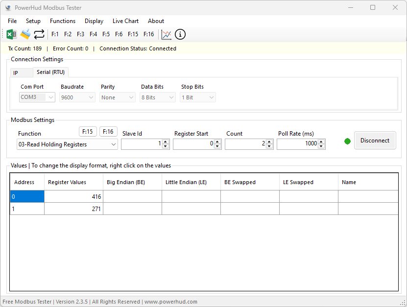
| Register | Raw Value | แปลผล |
|---|---|---|
| 0 | 419 | Humidity = 41.6 %RH |
| 1 | 271 | Temperature = 27.1 °C |

รีวิว
ยังไม่มีบทวิจารณ์