
คำอธิบาย
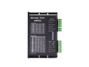
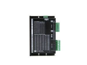
Stepper Driver รุ่น DM542-RS485 เป็นไดรเวอร์ดิจิทัลสำหรับมอเตอร์ 2 เฟส (2-Phase Stepper Motor)
สามารถควบคุมได้ทั้งจาก สัญญาณพัลส์ภายนอก (Pulse/Direction) และ สื่อสารผ่าน RS-485 Modbus RTU เพื่ออ่าน-เขียนพารามิเตอร์จากคอมพิวเตอร์, PLC หรือ HMI
Key Features
- ใช้ ชิป DSP 32 บิต ที่ออกแบบเฉพาะสำหรับการควบคุมมอเตอร์ ทำให้การทำงานของมอเตอร์ราบรื่น เสถียร และลดการหลุดสเต็ปได้อย่างมีประสิทธิภาพ
- รองรับสัญญาณอินพุต Pulse, Direction และ Enable และสามารถควบคุมผ่าน RS-485 Communication ได้
- เมื่อใช้งานในโหมดกำหนดตำแหน่งภายใน (Internal Position Mode) พอร์ต Pulse และ Direction สามารถใช้เป็นอินพุตของสัญญาณจากเซนเซอร์ได้
- ใช้อัลกอริธึมควบคุมที่ปรับให้เหมาะสม ช่วยลดความร้อนและแรงสั่นสะเทือนของมอเตอร์ ทำให้เครื่องจักรทำงานได้เร็วขึ้นและมีความเที่ยงตรงมากขึ้น
สเปคหลักของ DM542-RS485
| รายการ | รายละเอียด |
|---|---|
| แรงดันไฟเลี้ยง (VDC) | 20 – 50 V DC |
| กระแสขับต่อเฟส | 1.0 – 4.0 A (8 ระดับ) |
| โหมดการทำงาน | Position / Speed |
| ความละเอียดไมโครสเต็ปสูงสุด | 1 → 40,000 pulse/rev |
| ความถี่สัญญาณอินพุตสูงสุด | 200 kHz |
| อินพุต/เอาต์พุต | Opto-isolated |
| การลดกระแสอัตโนมัติ | ลดครึ่งหนึ่งเมื่อหยุดเกิน 1.5 s |
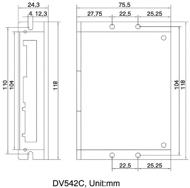
| ขนาดโดยประมาณ | 118 × 24.3 × 75.5 mm |
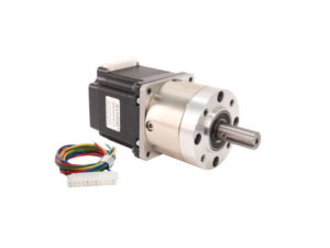
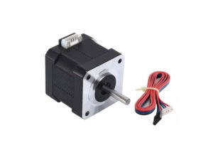
| มอเตอร์ที่รองรับ | 2-Phase, 42–60 mm frame |
การต่อสายและสัญญาณอินพุต
| สัญญาณ | หน้าที่ | รายละเอียด |
|---|---|---|
| PU+ / PU- | Step Pulse | ขอบขาลง (Falling Edge) ทำให้มอเตอร์หมุน 1 สเต็ป อินพุต 220 Ω |
| DR+ / DR- | Direction | สลับทิศการหมุน |
| MF+ / MF- | Enable / Free | ระดับ Low = ตัดกระแสขดลวด |
| COM24V | Common (เลือก 5 V หรือ 24 V) | รองรับ Common Anode หรือ Common Cathode |
| V+, V- | Power Input | 20–50 V DC |
| A+, A-, B+, B- | Motor Output | ต่อกับขดมอเตอร์ A/B |
ข้อควรระวัง (Warning Notes)
- แรงดันไฟฟ้าขาเข้า ต้องไม่เกิน DC50V
- ในโหมด Position ใช้สัญญาณพัลส์ขอบตก (falling edge) เป็นขอบที่มีผล
- หากอุณหภูมิเกิน 80°C ตัวไดรเวอร์จะหยุดทำงาน และไฟเตือน ALM จะติดค้าง
→ เมื่ออุณหภูมิลดลงต่ำกว่า 50°C ต้อง ปิด–เปิดเครื่องใหม่ เพื่อกลับมาทำงาน - หากมีการ ลัดวงจรหรือกระแสเกิน ไฟ ALM จะติด ตรวจสอบการต่อสายมอเตอร์และสาเหตุอื่น ๆ จากนั้นปิด–เปิดเครื่องใหม่
Dimension
การตั้งค่าผ่านสวิตช์ DIP
SW1–SW3 → ตั้งค่ากระแส
| Operating Current (A) | 1.0 | 1.2 | 1.5 | 2.0 | 2.5 | 3.0 | 3.5 | 4.0 |
|---|---|---|---|---|---|---|---|---|
| Peak Current (A) | 1.4 | 1.7 | 2.1 | 2.8 | 3.5 | 4.2 | 4.9 | 5.6 |
| SW1 | ON | OFF | ON | OFF | ON | OFF | ON | OFF |
| SW2 | ON | ON | OFF | OFF | ON | ON | OFF | OFF |
| SW3 | ON | ON | ON | ON | OFF | OFF | OFF | OFF |
SW4 → เลือกโหมด
- OFF = Microstep Mode
- ON = I/O Mode (Modbus Position หรือ Modbus Speed Mode)
SW5–SW8 → ตั้งไมโครสเต็ป (Subdivision / Speed)
Microstep (pulses/rev) | 200 | 400 | 800 | 1600 | 3200 | 6400 | 12800 | 25600 |
| Microstep (pulses/rev) | 1000 | 2000 | 4000 | 5000 | 8000 | 10000 | 20000 | 40000 |
|---|---|---|---|---|---|---|---|---|
| Speed (rpm) | 200 | 250 | 300 | 400 | 500 | 600 | 700 | 800 |
| SW5 | ON | OFF | ON | OFF | ON | OFF | ON | OFF |
| SW6 | ON | ON | OFF | OFF | ON | ON | OFF | OFF |
| SW7 | ON | ON | ON | ON | OFF | OFF | OFF | OFF |
| SW8 | OFF | OFF | OFF | OFF | OFF | OFF | OFF | OFF |
Modbus
คำอธิบายการแก้ไขพารามิเตอร์ภายในของ Modbus
-
พารามิเตอร์ PA0–PA70 จะตรงกับ Modbus RTU Address 0–70 (ฐานสิบ)
-
ตัวอย่าง:
ถ้าต้องการเปลี่ยนพารามิเตอร์สองตัว —-
เปลี่ยน PA5 = 250
-
เปลี่ยน PA32 = 2
ค่าที่เขียนใหม่นี้จะถูกเก็บไว้ชั่วคราวใน หน่วยความจำสื่อสาร (RAM) ของพอร์ตอนุกรมเท่านั้น
เมื่อ ปิด–เปิดเครื่องใหม่ ค่าทั้งหมดจะกลับไปเป็น ค่าเริ่มต้น (Default) เดิม
-
Operating Modes:
- SW4 OFF: External Pulse Mode
- SW4 ON:
- PA28 parameter 1: Internal Position Mode
- PA28 parameter 2: Internal Speed Mode
คำสั่ง Modbus มาตรฐาน
| Function Code | คำสั่ง | การใช้งาน |
|---|---|---|
| 03H | Read Holding Registers | อ่านค่าพารามิเตอร์หลายรายการ |
| 06H | Write Single Register | เขียนค่าพารามิเตอร์ 1 รายการ |
| CRC16 | ตรวจสอบข้อมูล | Polynomial = A001H |
ตัวอย่าง
-
อ่าน 2 พารามิเตอร์จาก PA5 เริ่มต้น:
01 03 00 05 00 02 D4 0A -
เขียนค่า 100 (0x0064) ไปยัง PA5:
01 06 00 05 00 64 98 20
พารามิเตอร์ภายในที่สำคัญ (DM542C / DV542C)
| รหัส | ชื่อพารามิเตอร์ | ช่วงค่า | ค่ามาตรฐาน | คำอธิบาย |
|---|---|---|---|---|
| PA28 | Internal Mode Select | 1–2 | 1 | 1 = Position, 2 = Speed |
| PA50 | Control Word | Bit 0–3 | – | สั่ง Run, Pause, Stop, Home |
| PA51–PA55 | Motion Parameter | – | – | กำหนด รอบ / พัลส์ / ความเร็ว / เร่ง-ลด |
| PA57 | Position Mode | 0–1 | 1 | 0 = Absolute , 1 = Relative |
| PA61–PA66 | Speed & Home Mode | – | – | เลือก I/O ควบคุม และ โหมด Homing (17,18,23,27,35) |
| PA99 | Save to Flash | – | – | เขียนค่า A1 เพื่อบันทึก |
1. ModBus Internal Position and Speed Control
ตารางนี้อธิบายพารามิเตอร์ PA ที่ใช้สำหรับการควบคุมตำแหน่งและความเร็วภายในผ่าน ModBus
| Parameter | Description |
| PA28 | 1: Internal position mode; 2: Internal speed mode. |
| PA50 | Control Word. ใช้สำหรับฟังก์ชันโหมดตำแหน่งภายใน:
|
| PA51 | Internal position setting (Revolutions). |
| PA52 | Internal position pulses per revolution. |
| PA53 | Internal position operation maximum speed (Unit: r/min). |
| PA54 | Acceleration time constant (Unit: milliseconds). |
| PA55 | Deceleration time constant (Unit: milliseconds). |
| PA56 | Jerk (S-curve) acceleration time constant (Default: 0). |
| PA57 | Internal position mode: 0 = Absolute position, 1 = Relative position. |
| PA58 | Set rated speed value. |
| PA59 | Homing high speed (Speed for finding the limit point). |
| PA60 | Homing low speed (Speed for finding the zero point). |
| PA61 | Control mode in speed mode:
|
| PA63 | Speed mode action selection:
|
| PA64 | Invert input active level (Default: 0 = ON is active). |
| PA65 | Pulse/Direction port function assignment for homing:
|
| PA66 | Homing mode selection (Supports modes 17, 18, 23, 27, 35). |
| PA66=17 | Mechanical Origin: Reverse travel limit switch.
Deceleration Point: Reverse travel limit switch. |
1. ModBus Internal Position and Speed Control DM542C-RS485
ตารางอธิบายพารามิเตอร์ PA ที่ใช้สำหรับการควบคุมตำแหน่งและความเร็วภายในผ่าน ModBus
| Parameter | Description |
| PA28 | 1: Internal position mode;
2: Internal speed mode. |
| PA50 | Control Word. ใช้สำหรับฟังก์ชันโหมดตำแหน่งภายใน:
|
| PA51 | Internal position setting (Revolutions). |
| PA52 | Internal position pulses per revolution. |
| PA53 | Internal position operation maximum speed (Unit: r/min). |
| PA54 | Acceleration time constant (Unit: milliseconds). |
| PA55 | Deceleration time constant (Unit: milliseconds). |
| PA56 | Jerk (S-curve) acceleration time constant (Default: 0). |
| PA57 | Internal position mode: 0 = Absolute position, 1 = Relative position. |
| PA58 | Set rated speed value. |
| PA59 | Homing high speed (Speed for finding the limit point). |
| PA60 | Homing low speed (Speed for finding the zero point). |
| PA61 | Control mode in speed mode:
|
| PA63 | Speed mode action selection:
|
| PA64 | Invert input active level (Default: 0 = ON is active). |
| PA65 | Pulse/Direction port function assignment for homing:
|
| PA66 | Homing mode selection (Supports modes 17, 18, 23, 27, 35). |
| PA66=17 | Mechanical Origin: Reverse travel limit switch.
Deceleration Point: Reverse travel limit switch. |
2. ModBus Parameter List DM542C-RS485
| Parameter / Name | Function | Range | Default |
| P-00 / Current Loop P-Gain | Proportional gain of the current loop. | 1000-9000 | 2000 |
| P-01 / Current Loop I-Gain | Integral gain of the current loop. | 10-100 | 25 |
| P-04 / Pulse Filter Coeff. | Smoothing filter for input pulses. | 1-2048 | 128 |
| P-10 / Enable Signal | Set enable signal active level (0 or 1). | 0-1 | 1 |
| P-11 / Pulse Active Edge | 0: Rising edge count; 1: Falling edge count. | 0-1 | 0 |
| P-12 / E-Gear Ratio Num. | Electronic gear ratio numerator. | 1-9999 | 1 |
| P-13 / E-Gear Ratio Den. | Electronic gear ratio denominator. | 1-9999 | 1 |
| P-14 / Pulse Mode Sel. | 0: Dual pulse (CW/CCW); 1: Pulse + Direction. | 0-1 | 1 |
| P-15 / Motor Direction | 0: Default forward direction; 1: Reverse. | 0-1 | 0 |
| P-18 / Software Version | Software version number. | ||
| P-20 / Customer Version | Customer version number. | – | 0 |
| P-28 / Operation Mode | When DIP set to internal mode: 1=Position; 2=Speed. | 1-2 | 1 |
| P-29 / Modbus Slave Addr. | Modbus slave address. | 1-255 | 1 |
| P-30 / Modbus Baud Rate | Default 96 (Baud rate 9600). | 3-1152 | 96 |
| P-31 / Modbus Parity | 0: None; 1: Odd; 2: Even. | 0-2 | 0 |
| P-33 / Modbus Data Length | Modbus data length. | 8-9 | 8 |
| P-34 / Modbus Stop Bit | Modbus stop bit. | 1-2 | 1 |
| P-35 / Restore Defaults | Set this value to 356 to restore defaults. | 0-10000 | 0 |
| P-37 / Current Gain Speed | Current gain speed. | 0-2000 | 250 |
| P-38 / Current Gain Coeff. | Current gain coefficient. | 0-20 | 7 |
| P-40 / Volt-Current Gain | 0: Max gain associated w/ voltage; 1: Not associated. | 0-1 | 0 |
| P-41 / DIP Speed 1 | Corresponds to the 1st speed in speed mode. | 1-1000 | 10 |
| P-42 / DIP Speed 2 | Corresponds to the 2nd speed in speed mode. | 1-1000 | 20 |
| P-50 / Control Word | Used for internal position mode function control. | 0-8 | 0 |
| P-51 / Travel Revolutions | Number of revolutions for travel. | 0-10000 | 10 |
| P-52 / Pulses per Rev. | Pulses per revolution for travel (used with P-51). | 0-10000 | 2000 |
| P-53 / Operating Speed | Constant speed segment speed (r/min). | 0-1500 | 500 |
| P-54 / Acceleration Time | Time to accelerate to rated speed (ms). | 0-10000 | 5000 |
| P-55 / Deceleration Time | Time to decelerate from rated speed (ms). | 0-10000 | 5000 |
| P-56 / Jerk Time | S-curve (Jerk) time. | 0-1000 | 0 |
| P-57 / Absolute/Relative | 0: Absolute position; 1: Relative position. | 0-1 | 1 |
| P-58 / Rated Speed | Rated speed (r/min). | 0-1500 | 1000 |
| P-59 / Homing High Speed | High speed for finding limit switch. | 0-1000 | 60 |
| P-60 / Homing Low Speed | Low speed for finding origin. | 0-1000 | 10 |
| P-61 / Speed Mode I/O En. | 0: Internal speed control; 1: DIP switch speed control. | 0-1 | 1 |
| P-63 / Speed Mode Action | 0: PU=Start/Stop, DR=Fwd/Rev; 1: PU=Fwd, DR=Rev. | 0-1 | 0 |
| P-64 / Input Active Level | Default: input port conducting (ON) is active. | 0-1 | 0 |
| P-65 / Pulse Input Func. | 0: Negative limit; 1: Positive limit. | 0-1 | 0 |
| P-66 / Homing Mode | Only supports modes: 17, 18, 23, 27, 35. | 0-100 | 17 |
การแจ้งเตือน (Alarm Code)
| ไฟ LED | ความหมาย | วิธีแก้ |
|---|---|---|
| แดงค้าง | Over-Current | ตรวจสอบสายมอเตอร์หรือโหลด |
| แดงกระพริบ × 2 | Over-Voltage | ตรวจแรงดัน > 50 V DC |
| แดงกระพริบ × 3 | Over-Temperature > 80 °C | ปิดเครื่องให้เย็น < 50 °C ก่อนรีสตาร์ต |
คำแนะนำการใช้งาน
- ตั้งค่า ID และ Baudrate ให้ตรงกับ PLC / Controller
- ใช้สาย RS-485 แบบ Shielded Twisted Pair และต่อลง GND ร่วม
- เขียนค่าพารามิเตอร์ทั้งหมดก่อน แล้วค่อยสั่ง Save ด้วย PA-99 = A1
- หลีกเลี่ยงการเขียนพารามิเตอร์ขณะมอเตอร์ทำงาน (เพราะ DSP จะหยุดชั่วขณะ)
- ติดตั้ง Heatsink หากใช้งานต่อเนื่องที่กระแสสูง
รีวิว
ยังไม่มีบทวิจารณ์